Construction method for building artificial rock plug body and water intake in reservoir

A construction method and water intake technology, which are applied in water conservancy projects, general water supply conservation, construction, etc., can solve the problems of rock plug blasting safety risks and hidden dangers, and achieve the effects of reduced engineering difficulty, high safety, and shortened construction period.

Inactive Publication Date: 2021-12-17
SHANGHAI MUNICIPAL ENG DESIGN INST GRP
View PDF4 Cites 0 Cited by
  • Summary
  • Abstract
  • Description
  • Claims
  • Application Information

AI Technical Summary

Problems solved by technology

However, this method must meet the following requirements: 1. It must be ensured that there is no risk of water inrush from the rock plug body to ensure the safety of tunnel construction personnel; 2. It must be ensured that the blasting will not cause structural damage to the completed tunnel lining and hydraulic structures. ;3. It must be ensured that the rock plug body is formed by one-time blasting, and the water intake after the blasting is complete; 4. It must be ensured that all explosives are completely detonated, and no underwater squibs can be left behind; The pit will not affect the operation of the water diversion project in the future
The above requirements must be met at the same time, otherwise it will bring greater safety risks or potential safety hazards to rock plug blasting
In order to reduce risks, detailed geological surveying and geological surveys, as well as a large amount of analysis and demonstration work are often required before rock plug blasting, which poses great challenges to all parties participating in the project

Method used


Image

  • Construction method for building artificial rock plug body and water intake in reservoir
  • Construction method for building artificial rock plug body and water intake in reservoir
  • Construction method for building artificial rock plug body and water intake in reservoir

Examples


Embodiment

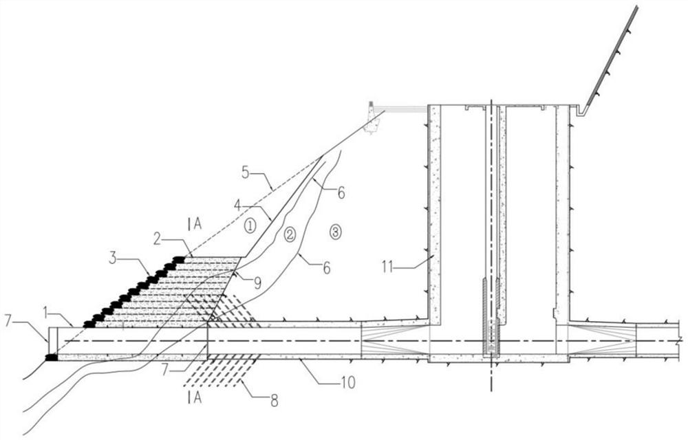
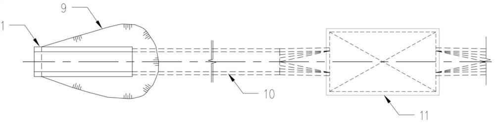
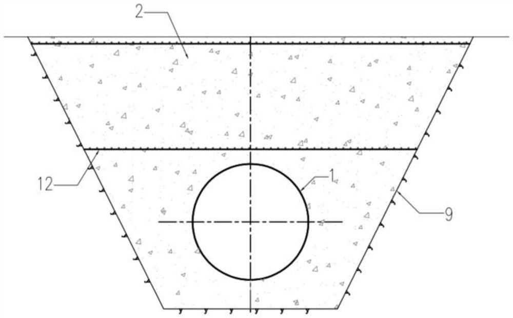
[0029] Such as Figure 1 ~ Figure 3 Shown, the construction method of building permanent artificial rock plug body and water intake described in the present embodiment in built reservoir, comprises the following steps:

[0030] (1) During the low water level window period of the reservoir, the strong weathered overburden layer on the surface of the underwater slope at the proposed water intake should be removed by means of underwater excavation and underwater blasting by grab boats to form underwater trenches;

[0031] (2) Flange covers are reserved at both ends of the prefabricated water intake pipe, and the prefabricated water intake pipe is sunk to the designated position in the trench in the form of an immersed tube, and the water intake pipe protrudes from the underwater slope by no less than 1.0m;

[0032] (3) Stack sand bags layer by layer on the edge of the underwater trench, with a height of 0.4m to 1.0m for each layer, and set the steel mesh above the water intake. ...


PUM


Abstract

The invention provides a construction method for building a permanent artificial rock plug body and a water intake in a built reservoir. The method comprises the following steps: in a low-water-level window period of the reservoir, removing a strongly weathered covering layer on the surface of an underwater side slope at the water intake to be built through underwater excavation and underwater blasting to form an underwater groove; then, sinking the prefabricated water taking opening with the flange cover plates reserved at the two ends into the groove in a pipe sinking mode; pouring underwater reinforced concrete to fill the groove to form the permanent artificial rock plug body and the water intake; under the protection of the permanent artificial rock plug body, constructing a diversion tunnel to the water intake, dismounting a reserved flange cover plate of the water intake and sequentially connecting the same with a diversion tunnel secondary lining structure, wherein communication between the reservoir and the diversion tunnel is achieved. Cofferdam construction or underwater rock plug blasting construction does not need to be conducted according to the traditional method, so that the applicability is wide, the safety is high, the investment is saved, the water flow condition of the water intake is good, the construction period cannot be limited by the low-water-level window period of the reservoir, and the construction period is shortened.

Description

technical field [0001] The invention belongs to the field of water conservancy engineering, and in particular relates to a construction method for constructing artificial rock plug bodies and water intakes in existing reservoirs in water diversion and water diversion projects. Background technique [0002] With the continuous development of my country's economic construction, more and more water diversion and water diversion projects need to build water intake tunnels to directly draw water from the built reservoirs. In order to ensure the water intake rate, the water intake generally needs to be set below the dead water level of the reservoir. In most cases, the construction party cannot directly lower the water level of the reservoir to the dead water level for the construction of the water intake, and even if the construction is carried out during the low water level window period of the non-flood season, the water intake is located at a depth of several meters to tens of...

Claims


Application Information

Patent Timeline
Patent Type & Authority Applications(China)
IPC IPC(8): E02B3/00E03B3/02
CPCE02B3/00E03B3/02Y02A20/108
Inventor 强健高程鹏祁峰王林
Owner SHANGHAI MUNICIPAL ENG DESIGN INST GRP
Why Eureka
Try Eureka