
Milling force measuring instrument based on thin film strain gauge

A strain gauge and measuring instrument technology, which is used in measuring/indicating equipment, metal processing mechanical parts, metal processing equipment, etc., can solve the problem of difficult to measure the weak strain signal on the tool holder surface, the weak strain signal on the tool holder surface, hysteresis and creep. and other problems, to achieve the effect of simple structure, wide practical range and convenient manufacturing

Pending Publication Date: 2021-12-17
UNIV OF ELECTRONICS SCI & TECH OF CHINA
View PDF11 Cites 4 Cited by
  • Summary
  • Abstract
  • Description
  • Claims
  • Application Information

AI Technical Summary

Problems solved by technology

[0005] The common resistive strain sensors on the market are mainly pasted resistance strain gauges, which need to be closely attached to the surface of the tested object with the help of an adhesive for measurement, but the combination of the adhesive and the tested object will bring certain hysteresis and creep problems
If the adhesive strain gauge is used to measure the surface strain of the tool holder to measure the cutting force, it will be accompanied by the actual processing characteristics: (1) high-speed rotation and high-frequency vibration during tool processing; (2) high temperature; (3) The high rigidity of the shank leads to weak strain signals on the surface of the shank; the defects of the adhesive strain gauge will be more obvious, and it is difficult to measure the weak strain signals on the surface of the shank

Method used


Image

  • Milling force measuring instrument based on thin film strain gauge
  • Milling force measuring instrument based on thin film strain gauge
  • Milling force measuring instrument based on thin film strain gauge

Examples


Embodiment Construction

[0030] The present invention will be further described below in conjunction with accompanying drawing and specific embodiment:

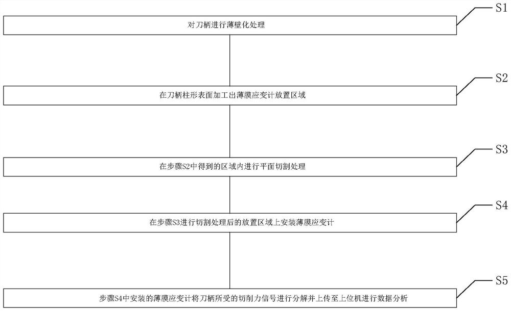
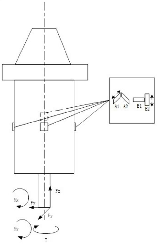
[0031] Such as Figure 1 to Figure 7 As shown, a kind of milling force measuring instrument based on thin-film strain gauge provided by the present invention comprises a tool holder, on which an electromechanical device is fixed, and the electromechanical device includes a battery, a thin-film strain gauge, a signal processing circuit and a signal transmitting device, and the batteries are respectively It is electrically connected with the film strain gauge, the signal processing circuit and the signal transmitting device. The battery is responsible for supplying energy, and the thin film strain gauge is responsible for sensing the strain signal on the surface of the tool holder due to the cutting force. The signal processing circuit collects and amplifies the signal measured by the thin film strain gauge, and the signal transmitting device transmits...


PUM


Abstract

The invention discloses a milling force measuring instrument based on a thin film strain gauge. The milling force measuring instrument comprises a cutter handle, an electromechanical device is fixed on the cutter handle, the electromechanical device comprises a battery, the thin film strain gauge, a signal processing circuit and a signal transmitting device, and the battery is electrically connected with the thin film strain gauge, the signal processing circuit and the signal transmitting device respectively. The battery is responsible for supplying energy, the thin film strain gauge is responsible for sensing a cutter handle surface strain signal generated by cutting force, the signal processing circuit is used for collecting and amplifying the signal measured by the thin film strain gauge, and the signal transmitting device is used for transmitting information processed by the signal processing circuit to a signal receiving device and uploading the information to an upper computer for data analysis.

Description

technical field [0001] The invention belongs to the technical field of cutting force measuring devices, and in particular relates to a milling force measuring instrument based on a thin film strain gauge. Background technique [0002] In the process of mechanical cutting, cutting force is an important parameter. By monitoring the magnitude and direction of cutting force, it can be used for the prediction and evaluation of tool wear and the quality of machined parts. At the same time, it can also guide the adjustment of processing parameters. Manufacturing is of great significance. [0003] The cutting force is generated at the cutting engagement point of the tool and the workpiece. According to Newton's third law, the cutting force can be measured at the workpiece end or the tool end. For milling, the cutting force of the workpiece end can be measured with a table-type dynamometer, but it cannot be widely used in production and processing due to its defects such as complica...

Claims


Application Information

Patent Timeline
Patent Type & Authority Applications(China)
IPC IPC(8): B23Q17/09
CPCB23Q17/0952
Inventor 丁杰雄胡翀赖俊杰吴宇舟段莹瑞王伟王林江林震王啸东
Owner UNIV OF ELECTRONICS SCI & TECH OF CHINA
Learn More