Initiating explosive device ignition circuit and module
An ignition circuit and pyrotechnics technology, applied in the field of pyrotechnics ignition, can solve the problems of increasing system volume, weight and system complexity, complex protection circuits, control signal jitter, etc., to expand the application range, eliminate influence, reduce Effect of Voltage Demand
- Summary
- Abstract
- Description
- Claims
- Application Information
AI Technical Summary
Problems solved by technology
Method used
Image
Examples
specific Embodiment 1
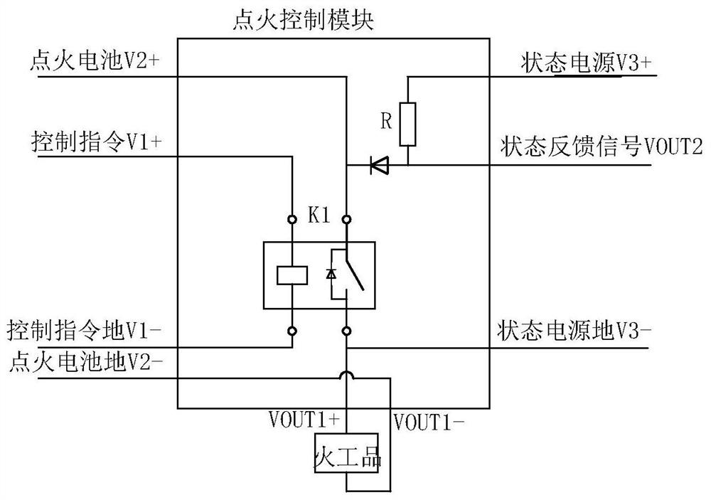
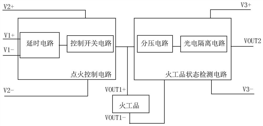
[0032] A pyrotechnic ignition circuit of the present application, such as figure 2 As shown, it includes the ignition control circuit and the pyrotechnics state detection circuit. The output of the ignition control circuit is connected to the input of the pyrotechnics state detection circuit. The ignition control circuit uses two power supplies, one is the power supply V1 for inputting the ignition command, and the other is It is the power supply V2 applied to the pyrotechnics, and the state detection circuit of the pyrotechnics uses a power supply to detect the state signal of the voltage applied to the pyrotechnics.
[0033] The ignition control circuit includes a delay circuit and a control switch circuit connected to each other. The delay circuit is used to delay and divide the ignition command signal to reduce the electromagnetic interference of the ignition command signal; The ignition command signal controls the switch to be turned on or off, so that the two ends of th...
specific Embodiment 2
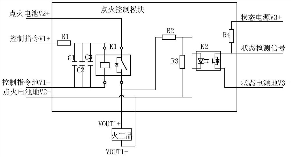
[0037] A pyrotechnic ignition circuit of the present application, such as image 3 As shown, it includes an RC delay circuit composed of a first resistor R1, a first capacitor C1, a second capacitor C2, and a third capacitor C3, wherein the first capacitor C1, the second capacitor C2, and the third capacitor C3 are connected in parallel, A parallel combination of capacitors is formed, and the first resistor R1 is connected in series with the parallel combination of capacitors to form an RC delay circuit.
[0038] Three capacitors are connected in parallel, and each capacitor is used to filter the magnetic interference signals of different frequency bands, so as to reduce the influence of the interference signals on the control switch circuit.
[0039] The two ends of the parallel combination of the capacitor are connected in parallel with the two input ends of the control switch circuit. The control switch circuit includes a magnetic isolation solid state relay K1, the two in...
specific Embodiment 3
[0054] A pyrotechnic ignition circuit of the present application, such as Figure 5 As shown, the difference from Embodiment 2 is that a second control switch circuit is also connected in series at the second end of the pyrotechnic device. In this circuit, the two ends of the pyrotechnic device are connected to the control switch circuit at the same time, which ensures the reliability of the power applied to the pyrotechnic device.
[0055] The second control switch circuit includes a magnetic isolation circuit, the two input ends on the input side of the magnetic isolation circuit are connected in parallel with the output end of the delay circuit, the first output end on the output side is connected to the second end of the pyrotechnic device, and the two input ends on the output side The second output end is connected to ignition power ground V2-.
[0056] Specifically, the magnetic isolation circuit includes a magnetic isolation solid state relay K4, the two input ends of ...
PUM
 Abstract
Description
Claims
Application Information
 - R&D
- Intellectual Property
- Life Sciences
- Materials
- Tech Scout
- Unparalleled Data Quality
- Higher Quality Content
- 60% Fewer Hallucinations
Browse by: Latest US Patents, China's latest patents, Technical Efficacy Thesaurus, Application Domain, Technology Topic, Popular Technical Reports.
© 2025 PatSnap. All rights reserved.Legal|Privacy policy|Modern Slavery Act Transparency Statement|Sitemap|About US| Contact US: help@patsnap.com


