A low-power current divider
A low-power, current technology, applied in instruments, adjusting electrical variables, control/regulating systems, etc., can solve the problems of occupation, large chip area, and increase the complexity of circuit design, to overcome high dependence and simple structure Effect
- Summary
- Abstract
- Description
- Claims
- Application Information
AI Technical Summary
Problems solved by technology
Method used
Image
Examples
Embodiment Construction
[0009] Below in conjunction with accompanying drawing, technical solution of the present invention is described in detail:
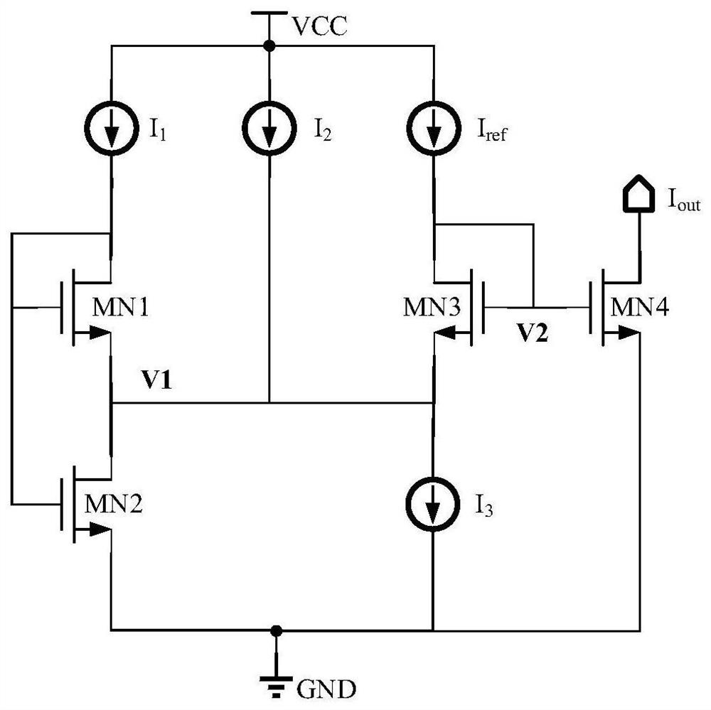
[0010] The current divider circuit proposed by the present invention is as figure 1 shown. figure 1 Among them, VCC is the power rail in the high-voltage area of the circuit, GND is the power rail in the low-voltage area, and all NMOS transistors work in the sub-threshold area. The first input current I 1 flows through the first NMOS transistor MN1, then
[0011] V of the first NMOS transistor MN1 GS1 The voltage can be derived as:
[0012]
[0013] According to Kirchhoff's current law, the total current flowing into the V1 node is equal to I 1 +I 2 +I ref , the current of the third current source I3 is equal to I 1 +I ref , then the current flowing through the second NMOS transistor MN2 is equal to I 2 , then the V of the second NMOS transistor MN2 GS2 Voltage can be expressed as:
[0014]
[0015] According to formula (1) and formul...
PUM
 Abstract
Description
Claims
Application Information
 - Generate Ideas
- Intellectual Property
- Life Sciences
- Materials
- Tech Scout
- Unparalleled Data Quality
- Higher Quality Content
- 60% Fewer Hallucinations
Browse by: Latest US Patents, China's latest patents, Technical Efficacy Thesaurus, Application Domain, Technology Topic, Popular Technical Reports.
© 2025 PatSnap. All rights reserved.Legal|Privacy policy|Modern Slavery Act Transparency Statement|Sitemap|About US| Contact US: help@patsnap.com


