Circuit breaker switch energy storage device and circuit breaker

A technology of circuit breaker switch and energy storage device, which is applied to the power device, electric switch, protection switch operation/release mechanism and other directions inside the switch, and can solve the problems of affecting the energy release effect, energy loss, affecting the opening and closing of the circuit breaker, etc. , to achieve the effect of smooth opening or closing process of the energy release drive switch

Pending Publication Date: 2021-12-07
JIANGNAN YIFAN MOTOR
View PDF0 Cites 0 Cited by
  • Summary
  • Abstract
  • Description
  • Claims
  • Application Information

AI Technical Summary

Problems solved by technology

[0002] In the electronically controlled high-voltage circuit breaker, it is necessary to store energy in the switch so that the switch contact can immediately cut off the circuit when the line is faulty or overloaded, so as to prevent the contact from being burnt due to arcing and causing the switch to be scrapped. In the prior art, the switch storage The energy device drives the large ring gear through the deceleration of the motor. The large ring gear cooperates with the ratchet and the pawl on the inner ring to transmit the power to the energy storage element connected to the circuit breaker to realize the energy storage of the switch. At this time, the energy storage element will drive the ratchet in the opposite direction to achieve one-way transmission without transmission to the large ring gear. However, the structure in the prior art reverses too quickly when the energy storage element releases energy, which will cause the pawl to reverse and the ratchet to resist. connected, resulting in energy loss, affecting the energy release effect, which in turn will affect the opening and closing of the circuit breaker switch

Method used

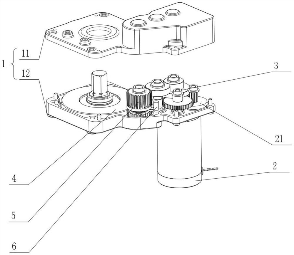
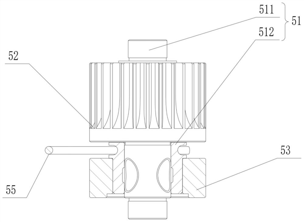
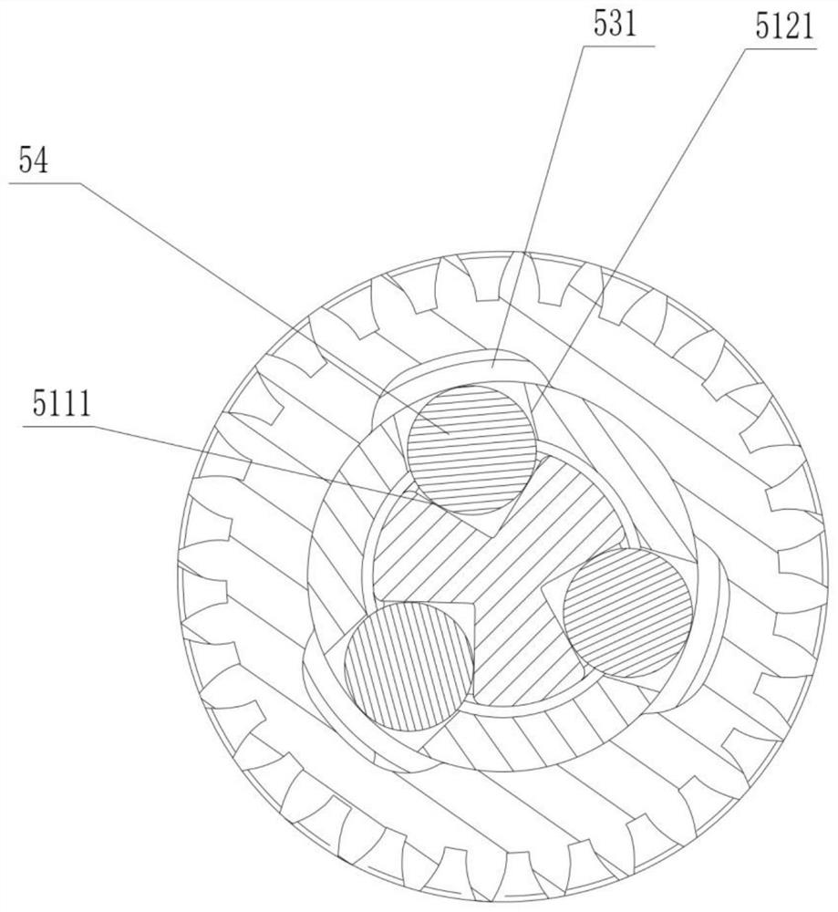

Image

  • Circuit breaker switch energy storage device and circuit breaker
  • Circuit breaker switch energy storage device and circuit breaker
  • Circuit breaker switch energy storage device and circuit breaker

Examples


Embodiment Construction

[0032] The technical solution of the present invention will be further described below with reference to the drawings and embodiments. It will be appreciated that the specific embodiments described herein are merely illustrative of the invention and are not limited thereto. It will also be also to be explained, and only the parts associated with the present invention are shown in the drawings rather than all.

[0033] In the description of the invention, it is to be noted that the term "mount", "connected", "connection", such as a fixed connection, unless otherwise expressly specified and defined, unless otherwise expressly specified and defined. Connection; may be mechanical connection, or electrical connection; may be directly connected, or indirectly connected by an intermediate medium, which can be in the inside of the two elements. The specific meaning of the above terms in the present invention will be appreciated to those skilled in the art.

[0034] In the present inventio...


PUM


Abstract

The invention relates to the technical field of circuit breakers, in particular to a circuit breaker switch energy storage device and a circuit breaker. The circuit breaker switch energy storage device comprises a mounting shell, a driving part, a reduction gear set, an energy storage gear and a clutch, and the mounting shell is provided with a mounting cavity; the driving piece is arranged in the mounting shell in a penetrating manner; the reduction gear set is arranged in the mounting cavity and is in transmission connection with the output end of the driving part; the clutch is in transmission connection with the reduction gear set, the energy storage gear is in transmission connection with the clutch, the clutch is configured to allow power output by the reduction gear set to be transmitted to the energy storage gear and prevent power output by the energy storage gear from being transmitted to the reduction gear set, and the energy storage gear is used for driving a main shaft of a circuit breaker switch. And then the elastic energy storage element is driven to store energy. In the energy releasing process of the circuit breaker switch energy storage device, the energy storage gear rotates, power cannot be transmitted to the reduction gear set, and the switching-on or switching-off process is smoother.

Description

Technical field [0001] Technical Field The present invention relates to a circuit breaker, in particular, it relates to a circuit breaker and a circuit breaker switching energy storage device. Background technique [0002] Electronically controlled high pressure disconnection device, it is necessary to switch the line to achieve a storage or troubleshooting overload switching contacts can immediately cut off the circuit, the contacts to prevent arcing and burning of contacts is generated, resulting in the switch scrap, prior art switch reservoir energy means through the driven gear for driving the motor gear reducer, the large ring gear of the power transmission with the energy storage element is connected to the disconnect switch through which the inner ratchet pawl arranged to effect switching energy storage, energy release switch when the energy storage element in the opposite direction will drive the ratchet wheel, one-way transmission, Tai ring gear is not transmitted, but t...

Claims


Application Information

Patent Timeline
Patent Type & Authority Applications(China)
IPC IPC(8): H01H3/30H01H71/10
CPCH01H3/3015H01H71/10
Inventor 陈渊技
Owner JIANGNAN YIFAN MOTOR
Why Eureka
Try Eureka