Backlight module and display device thereof
A technology of backlight module and light, which is applied in optics, nonlinear optics, instruments, etc., can solve the problems of display device failure, dark lines, etc., and achieve the effect of avoiding mutual interference
- Summary
- Abstract
- Description
- Claims
- Application Information
AI Technical Summary
Problems solved by technology
Method used
Image
Examples
Embodiment 1
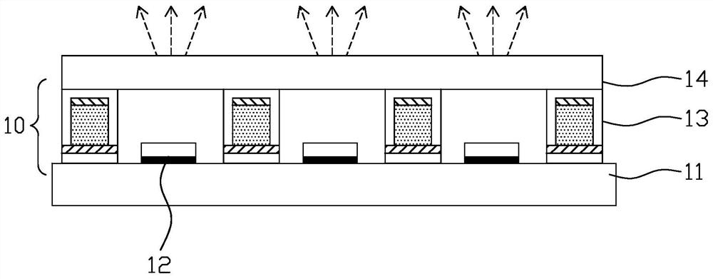
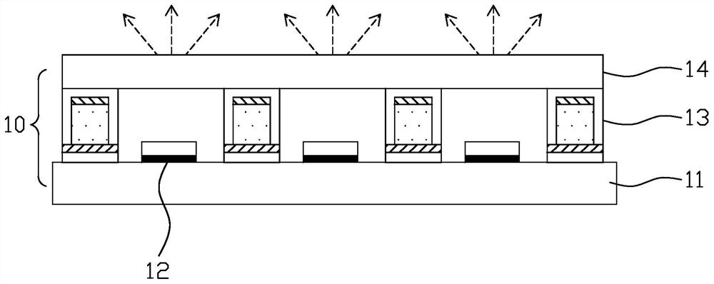
[0033] figure 2 is a schematic structural diagram of the backlight module in the first state of the first embodiment of the present invention, image 3 is a schematic structural diagram of the backlight module in the second state in the first embodiment of the present invention, Figure 4 is the top-view structural schematic diagram of the backlight module in the first embodiment of the present invention, Figure 5 is a schematic diagram of the cross-sectional structure at the edge of the isolation structure in the first embodiment of the present invention, such as Figure 2 to Figure 5 As shown, a backlight module provided by the first embodiment of the present invention includes a direct-type lamp panel 11, a plurality of light emitters 12 disposed on the direct-type lamp panel 11, and an isolation structure 13 (cup), and the isolation structure 13 will be more The light emitters 12 are spaced apart, and the isolation structure 13 can be switched between transparent and n...
Embodiment 2
[0043] Image 6 is a schematic structural diagram of the backlight module in the first state in the second embodiment of the present invention, Figure 7 is a schematic structural diagram of the backlight module in the second state of the second embodiment of the present invention, Figure 8 is a schematic diagram of the cross-sectional structure at the edge of the isolation structure in the second embodiment of the present invention, such as Figure 6-Figure 8 As described above, the backlight module provided in the second embodiment of the present invention is the same as that in the first embodiment ( Figure 2 to Figure 5 ) is basically the same as the backlight module in Two electro-birefringence layers 142, the top of the diffusion plate 14 is provided with a fifth transparent electrode 143 covering the receiving groove 14a, the top of the fifth transparent electrode 143 is provided with a protective layer 144 covering the fifth transparent electrode 143, the fourth tr...
Embodiment 3
[0050] Figure 10 is a schematic structural diagram of the backlight module in the first state in the third embodiment of the present invention, Figure 11 is a schematic cross-sectional structure diagram of the isolation structure at the first conductive pin in the third embodiment of the present invention, Figure 12 is a schematic cross-sectional structure diagram of the isolation structure at the second conductive pin in the third embodiment of the present invention, as shown in Figure 10-Figure 12As shown, the backlight module and the display device provided in the third embodiment of the present invention are the same as those in the first embodiment ( Figure 2 to Figure 5 ) in the backlight module and the display device are basically the same, the difference is that in this embodiment, the second transparent support structure 132 The transparent electrodes 134 cover the top and side walls of the second transparent support structure 132, so that the distance between ...
PUM
 Abstract
Description
Claims
Application Information
 - R&D
- Intellectual Property
- Life Sciences
- Materials
- Tech Scout
- Unparalleled Data Quality
- Higher Quality Content
- 60% Fewer Hallucinations
Browse by: Latest US Patents, China's latest patents, Technical Efficacy Thesaurus, Application Domain, Technology Topic, Popular Technical Reports.
© 2025 PatSnap. All rights reserved.Legal|Privacy policy|Modern Slavery Act Transparency Statement|Sitemap|About US| Contact US: help@patsnap.com


