Pumping truss type suction dredger and mounting method

A dredging machine and truss-type technology, applied in separation methods, chemical instruments and methods, feeding/discharging devices of settling tanks, etc., can solve the problems of low sludge cleaning efficiency, reduce rework, and prevent sludge The effect of overflowing and ensuring the quality of the project

Inactive Publication Date: 2021-12-07
QINGDAO INSTALLATION & CONSTR
View PDF5 Cites 0 Cited by
  • Summary
  • Abstract
  • Description
  • Claims
  • Application Information

AI Technical Summary

Problems solved by technology

[0004] The purpose of the present invention is to solve the problem of low sludge cleaning efficiency in the prior art, and propose a pump suction truss type suction dredger

Method used


Image

  • Pumping truss type suction dredger and mounting method
  • Pumping truss type suction dredger and mounting method
  • Pumping truss type suction dredger and mounting method

Examples


Embodiment 1

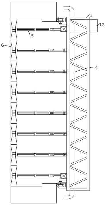
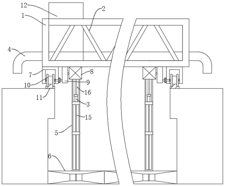
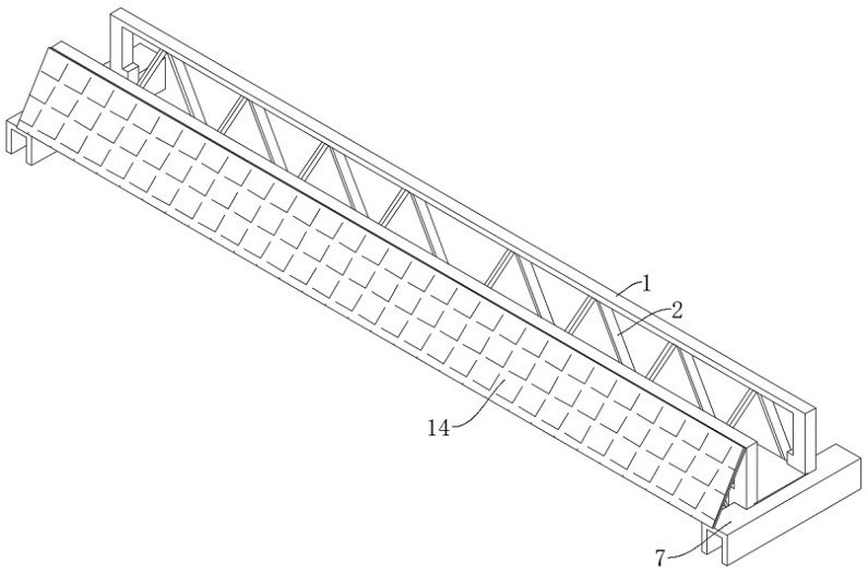
[0037] Embodiment one: refer to Figure 1-Figure 6 , a pump-suction truss-type dredger, including a horizontal truss 1, also includes: an end beam 7 fixedly connected to the bottom of the horizontal truss 1, the end beam 7 is provided with a driving part for driving the horizontal truss 1 to move; fixed on The steel frame 5 at the bottom of the horizontal truss 1; the mud scraping box 6 fixedly connected to the bottom of the steel frame 5, the mud scraping box 6 is provided with two connected trapezoidal grooves 602, and the mud scraping box 6 is provided with a mud collecting groove 601, The steel frame 5 is provided with a dredge pump 3, the input end of the dredge pump 3 is fixedly connected with a first pipeline 15, and the end of the first pipeline 15 away from the dredge pump 3 runs through the top of the mud scraping box 6 and extends to the mud collection tank 601 Inside: the mud discharge pipe 4 fixedly connected to the horizontal truss 1, the output end of the dredge...

Embodiment 2

[0045] Embodiment 2: An installation method of a pump-suction truss-type dredger adopts the following steps: Step 1: Take safety measures and environmental protection measures: Participating construction personnel must be familiar with safe operating procedures, and technical personnel shall carry out technical Safety disclosure; safety signs and warning signs are set up in the construction area, fences are set up around the filter pool, and signs are pasted on the equipment pipelines to prevent misuse; personal labor protection articles and safety protection measures are used correctly; special types of work must be certified; hoisting operations During the hoisting process, no one is allowed to stand under the jib and within the turning radius of the crane; temporarily use electricity on the construction site The relevant provisions of the JGJ "Technical Specifications for Temporary Electricity Use at Construction Sites" should be strictly followed. The installation, maintena...


PUM


Abstract

The invention discloses a pumping truss type suction dredger and a mounting method, and belongs to the technical field of sewage treatment. The pumping type truss suction dredger comprises a horizontal truss, and further comprises an end beam fixedly connected to the bottom of the horizontal truss, a steel frame and a mud scraping box; and a driving part used for driving the horizontal truss to move is arranged on the end beam; the steel frame is fixed at the bottom of the horizontal truss; the sludge scraping box is fixedly connected to the bottom of the steel frame; and sludge is guided through the sludge scraping box, so that the sludge is prevented from overflowing all around, the situation that the overflowing sludge is separated from the adsorption range of the suction dredger is avoided, and the sludge treatment effect is prevented from being reduced. The key in construction, namely, the construction method of the pumping type truss type suction dredger, is researched; a set of comprehensive construction technology for mounting the pumping truss type suction dredger is formed, the engineering quality is guaranteed, the reworking phenomenon is reduced, the engineering cost is saved, the mounting technology is simple, operation is convenient, and the engineering quality is easy to guarantee.

Description

technical field [0001] The invention relates to the technical field of sewage treatment, in particular to a pump-suction truss-type dredge and an installation method. Background technique [0002] With the rapid development of society, the recycling of urban domestic sewage and production wastewater is an increasingly urgent need for the social situation of increasingly scarce water resources; it is also an important measure to further improve regional environmental sanitation, reduce water pollution and protect the environment. Pump suction truss type Suction dredger is the core equipment of urban water treatment unit. [0003] In the prior art, when the dredger is processing the sludge at the bottom of the pool, the sludge often overflows to the surroundings in the pool, resulting in a reduced sludge cleaning effect, and the existing pump-suction truss-type dredge requires more labor for installation. , so the cost is higher, so it is necessary to design a pump-suction tr...

Claims


Application Information

Patent Timeline
Patent Type & Authority Applications(China)
IPC IPC(8): B01D21/24
CPCB01D21/245
Inventor 李凯常启文卞嘉夫原艺吴春雷黄国旗
Owner QINGDAO INSTALLATION & CONSTR
Why Eureka
Try Eureka