An oil control valve with a feedback oil circuit inside
An oil control valve and oil circuit technology, applied in valve devices, mechanical equipment, engine components, etc., can solve problems such as slow response speed and large oil loss, reduce oil loss, speed up adjustment, and maintain phase. stable effect
- Summary
- Abstract
- Description
- Claims
- Application Information
AI Technical Summary
Problems solved by technology
Method used
Image
Examples
Embodiment 1
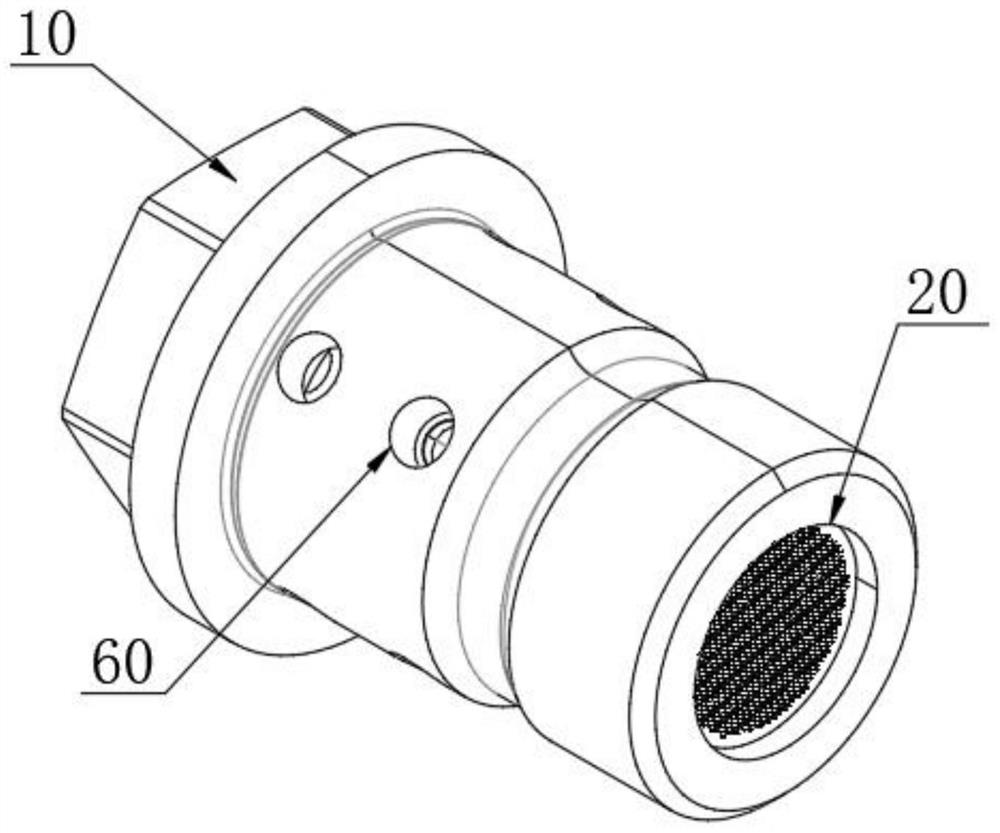
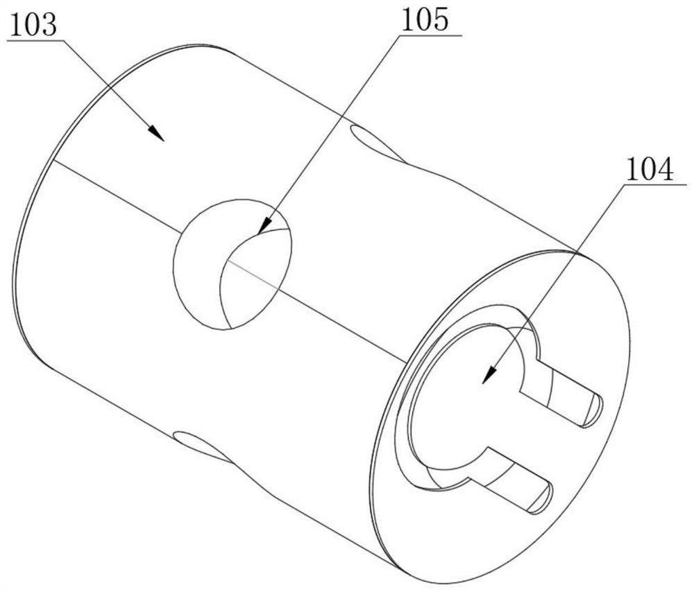
[0031] see Figure 1-3 As shown, an oil control valve with an internal feedback oil circuit includes a valve body 10, an oil inlet 20 is opened on one side of the valve body 10, and the inner two sides of the valve body 10 are divided into A oil passage and B oil passage The oil passage A and the oil passage B are respectively connected to the oil passage A and the oil passage B of the driver. An oil inlet assembly is arranged on the right side of the inside of the valve body 10, and a bushing 30 is arranged inside the valve body 10. A valve sleeve 40 is provided inside, the right side of the valve sleeve 40 is in contact with the left side of the oil inlet assembly, and the left side of the valve sleeve 40 is connected with the inside of the valve body 10 through the circlip 50. The reversing rod assembly, and the surfaces of the valve sleeve 40 and the valve body 10 are provided with several oil outlet holes 60. The reversing rod assembly includes a first reversing rod 101 a...
Embodiment 2
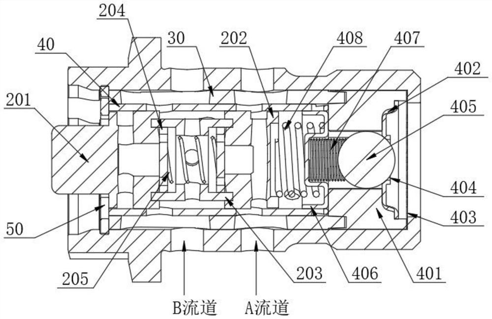
[0033] see Figure 4-5 As shown, another preferred solution in the present invention, the reversing rod assembly further includes a third reversing rod 201 and a fourth reversing rod 202, and both the third reversing rod 201 and the fourth reversing rod 202 are located in the valve The interior of the sleeve 40 is movably arranged, a second connecting sleeve 203 is arranged between the third reversing rod 201 and the fourth reversing rod 202, and steel sheets 204 are arranged on both sides inside the second connecting sleeve 203. The sheets 204 are all slidably arranged inside the second connecting sleeve 203 , a spring one 205 is arranged between the opposite sides of the two steel sheets 204 , and the two ends of the spring one 205 are respectively fixed to the opposite sides of the two steel sheets 204 For connection, the surface of the second connection sleeve 203 is provided with a second oil guide hole 206 , and the second oil guide hole 206 communicates with the interio...
Embodiment 3
[0035] see Figure 6-7As shown, another more preferred solution in the present invention, the reversing rod assembly further comprises a fifth reversing rod 301 and a sixth reversing rod 302, and the fifth reversing rod 301 and the sixth reversing rod 302 are both located at The inside of the valve sleeve 40 is movably arranged, a third connecting sleeve 303 is arranged between the fifth reversing rod 301 and the sixth reversing rod 302, and steel sleeves 304 are movably arranged on both sides inside the third connecting sleeve 303. The two steel sleeves 304 are all concave parts, the notches of the two steel sleeves 304 are opposite to each other, and a second spring 307 is arranged between the opposite notches of the two steel sleeves 304, and the two ends of the second spring 307 are respectively connected to the two steel sleeves. The interior of 304 is fixedly connected, and the surface of the third connection sleeve 303 is respectively provided with a third oil guide hol...
PUM
 Abstract
Description
Claims
Application Information
 - R&D
- Intellectual Property
- Life Sciences
- Materials
- Tech Scout
- Unparalleled Data Quality
- Higher Quality Content
- 60% Fewer Hallucinations
Browse by: Latest US Patents, China's latest patents, Technical Efficacy Thesaurus, Application Domain, Technology Topic, Popular Technical Reports.
© 2025 PatSnap. All rights reserved.Legal|Privacy policy|Modern Slavery Act Transparency Statement|Sitemap|About US| Contact US: help@patsnap.com


