
Light source assembly and observation system for time difference incubator

A light source component and observation system technology, which is applied in the direction of tissue cell/virus culture device, specific-purpose bioreactor/fermenter, bioreactor/fermenter combination, etc., can solve the lack of three-dimensional and layered images, It is difficult to accurately identify problems such as embryos, so as to avoid repeated focusing, reduce light damage, and ensure accuracy

Pending Publication Date: 2021-12-03
重庆市盛佰昱科技有限公司
View PDF0 Cites 0 Cited by
  • Summary
  • Abstract
  • Description
  • Claims
  • Application Information

AI Technical Summary

Problems solved by technology

[0005] Aiming at the technical problem that the existing time-lag incubator adopts the illuminating lamp to observe the embryo after concentrating the light, the obtained image lacks three-dimensional sense and layering, and it is difficult to accurately distinguish the shape of the embryo; the invention provides a light source assembly and an observation The system can make the image of biological tissue obtained by the microscopic camera have a sense of three-dimensionality and layering, so as to accurately distinguish the shape of biological tissue and ensure the accuracy of biological tissue evaluation, analysis and screening

Method used


Image

  • Light source assembly and observation system for time difference incubator
  • Light source assembly and observation system for time difference incubator
  • Light source assembly and observation system for time difference incubator

Examples


Embodiment 1

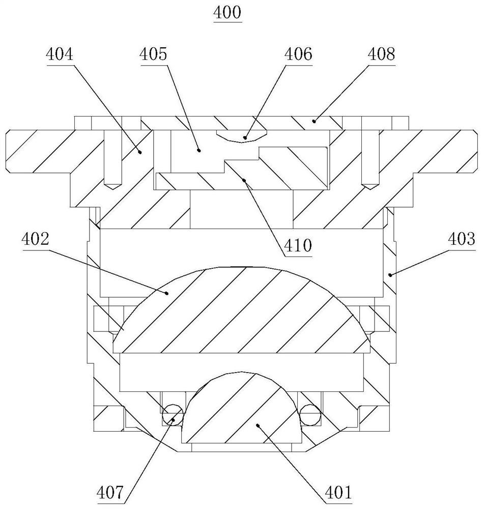
[0042] combine figure 1 , this embodiment provides a light source assembly for a time-lag incubator, including a first light-gathering portion 401, and a light-decaying sheet 410 is provided on the light-incident side of the first light-gathering portion 401, and the light-attenuating sheet 410 is arranged along the The light-attenuating sheet 410 is provided with a plurality of light-transmitting parts 411 sequentially in the longitudinal direction, and the light transmittance of the plurality of light-transmitting parts 411 increases sequentially along the longitudinal direction of the light-attenuating sheet 410 .

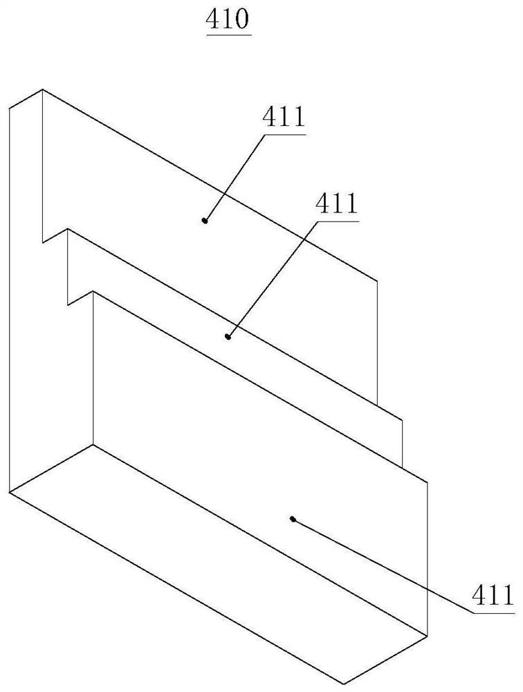
[0043] combine figure 2 Specifically, the number of the light-transmitting parts 411 is three, which simplifies the structure of the light-attenuating sheet 410 while ensuring that the image taken by the microscopic camera 310 has a sense of three-dimensionality and layering.

[0044] Preferably, the light transmittances of the three light-transmitting parts 4...

Embodiment 2

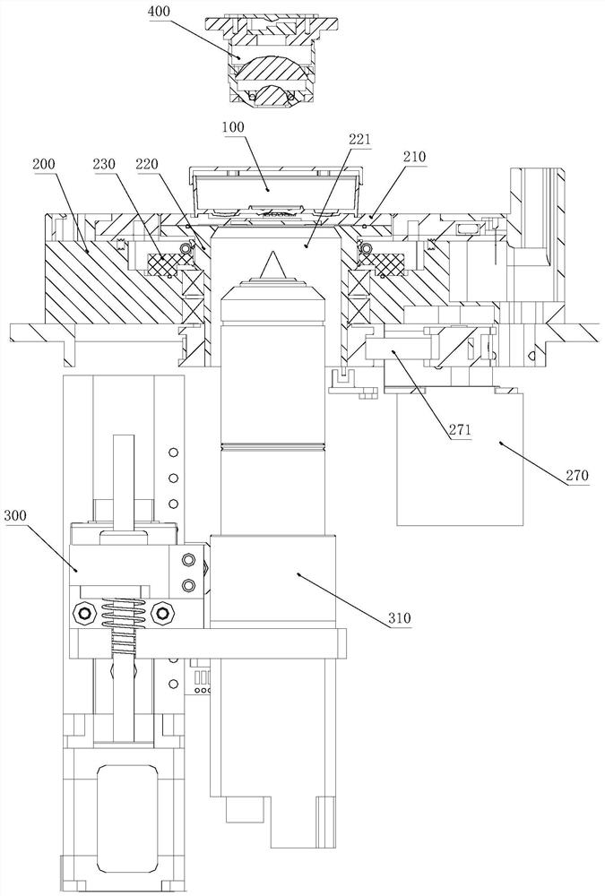
[0054] combine image 3 , based on the structure and working principle of the light source assembly 400 for the time-lag incubator described in Embodiment 1, this embodiment provides an observation system for the time-lag incubator, including the time-lag incubator described in Embodiment 1 The light source assembly 400 of the incubator also includes a microscopic camera 310, a linear drive mechanism 300 and a rotating shaft 220 for rotationally connecting with the culture cavity bottom plate 200, the upper end of the rotating shaft 220 is used to support the culture dish 100, and the rotating shaft 220 can rotate around its own axis; the middle part of the rotating shaft 220 is provided with an observation channel 221, and the linear drive mechanism 300 is used to drive the microscopic camera 310 along the axis of the first focusing part 401 in the observation channel 221 move.

[0055] combine Figure 4 , the linear drive mechanism 300 includes a lead screw 301 , a slider ...


PUM

PropertyMeasurementUnit
transmittivityaaaaaaaaaa

Abstract

The invention discloses a light source assembly and an observation system for a time difference incubator, and relates to the technical field of biological tissue culture. The light source assembly comprises a first light condensation part, a light attenuation piece is arranged on the light incidence side of the first light condensation part, a plurality of light transmitting parts are sequentially arranged on the light attenuation piece in the length direction of the light attenuation piece, and the light transmittance of the light transmitting parts is sequentially increased in the length direction of the light attenuation piece. The light source assembly is matched with a microcamera to shoot a biological tissue image with stereoscopic impression and layering sense, so that the form of a biological tissue is accurately judged, and the accuracy of evaluation analysis and screening of the biological tissue is ensured. The observation system comprises the light source assembly, a rotating assembly for driving a culture dish to rotate and the microcamera, repeated focusing of a microcamera system can be avoided, the definition of shot images is ensured, the images have the stereoscopic impression and the layering sense, so that the form of the biological tissue is accurately distinguished, and the accuracy of the evaluation analysis and the screening of the biological tissue is ensured.

Description

technical field [0001] The invention relates to the technical field of biological tissue culture, in particular to a light source assembly and an observation system for a jet-lag incubator. Background technique [0002] In Vitro Fertilization (In Vitro Fertilization) refers to the technology in which mammalian sperm and eggs complete the fertilization process in an artificially controlled environment outside the body. It is abbreviated as IVF in English. The existing in vitro culture of human embryos is achieved by placing the culture dish containing the embryos in a time-lag incubator or a conventional carbon dioxide incubator, while ensuring the temperature, humidity and cleanliness of the culture environment. [0003] Among them, the time difference incubator can provide a relatively closed culture and development environment for embryos, close to the mother's uterus, and can realize real-time monitoring and control adjustment of the temperature, CO2 and O2 concentration ...

Claims


Application Information

Patent Timeline
Patent Type & Authority Applications(China)
IPC IPC(8): C12M3/00C12M1/22C12M1/34G01N21/84
CPCC12M21/08C12M23/10C12M41/46G01N21/84
Inventor 蓝湘源古玉琼
Owner 重庆市盛佰昱科技有限公司
Learn More