Path optimization method for concrete 3D printing
A technology of 3D printing and path optimization, applied in the field of concrete 3D printing, can solve the problems of excessive printing breakpoints, frequent head rises, poor molding quality of 3D printing components, etc., to improve speed and quality, shorten empty strokes, and reduce inflection points. Effect
- Summary
- Abstract
- Description
- Claims
- Application Information
AI Technical Summary
Problems solved by technology
Method used
Image

Examples
Embodiment Construction
[0038] The present invention is described in further detail below in conjunction with embodiment.
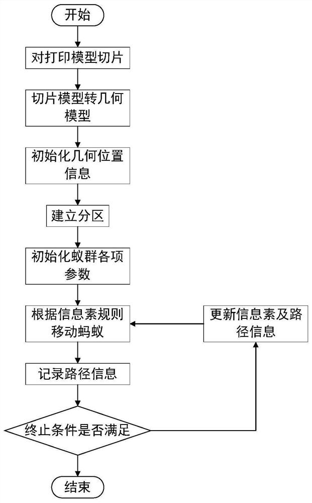
[0039] refer to figure 1 , the specific steps of the present invention are described in detail.
[0040] Step 1: Slicing the printed model.
[0041] Step 1: In the acquisition process of this method, the geometric data (length, width, height, etc.) of the printing member is first read out using a measuring tool, then a printing model is established based on the collected data, and finally the established model is sliced using Cura software.
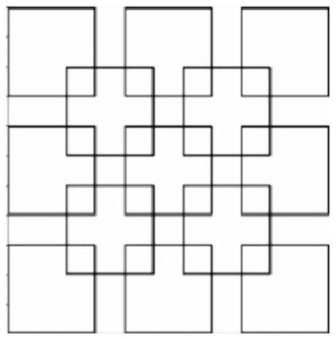
[0042] Step 2: Convert the sliced model into a geometric model.
[0043] Said step two: (1) delete the information in the slice model that does not need to be printed; (2) extract each geometric point in the slice model; (3) reduce the geometric data of the slice model collected in proportion , making the established geometric model easy to handle. Such as figure 2 .
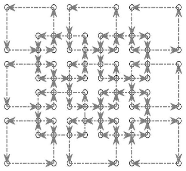
[0044] Step 3: Initialize the position information of the geo...
PUM
 Abstract
Description
Claims
Application Information
 - Generate Ideas
- Intellectual Property
- Life Sciences
- Materials
- Tech Scout
- Unparalleled Data Quality
- Higher Quality Content
- 60% Fewer Hallucinations
Browse by: Latest US Patents, China's latest patents, Technical Efficacy Thesaurus, Application Domain, Technology Topic, Popular Technical Reports.
© 2025 PatSnap. All rights reserved.Legal|Privacy policy|Modern Slavery Act Transparency Statement|Sitemap|About US| Contact US: help@patsnap.com