
Full-automatic numerical control corner splicing machine and corner splicing method thereof

A fully automatic, angle forming machine technology, used in hand-held tools, workpiece clamping devices, manufacturing tools, etc., can solve the problems of prolonged processing time, low internal angle positioning accuracy, lead screw wear, etc., to improve operating efficiency and accuracy. , Accurate and reliable internal angle positioning, eliminating the effect of hydraulic oil temperature rise

Pending Publication Date: 2021-12-03
济南康宏机械有限公司
View PDF0 Cites 1 Cited by
  • Summary
  • Abstract
  • Description
  • Claims
  • Application Information

AI Technical Summary

Problems solved by technology

Although the existing corner forming machine can process the corner forming of door and window profiles, in the process of practical application, it is still found that there are some deep-seated technical problems that need to be further studied and solved in terms of technical structure, which are specifically reflected in the following aspects: 1. It is time-consuming and labor-intensive to adjust the height of the corner knives. Due to the different structural designs of the corners that need to be grouped, the positions that need to be hit are different. Therefore, the height of the corner knives needs to be adjusted according to the design requirements of the profile. However, the height adjustment of the existing corner knives mainly relies on manual work. Adjustment, manual adjustment is not only time-consuming and labor-intensive, but also difficult to guarantee the adjustment accuracy; second, the existing corner knife structure cannot meet single-knife impact or impact at any point, and the existing corner knife structure is vertically aligned in a slideway. Generally, two groups of corner knives are set in the slideway, and the two groups of corner knives work together, so it is impossible to realize a single group of corner knives to hit the corner. The existing corner group machines only have custom-made knives or disassembled group corner knives to realize single-knife group corners , which will undoubtedly increase the cost and prolong the processing time, and with the diversification of profile structure design and the design of special-shaped corner codes, there are more and more requirements for this kind of corner grouping; the third is the feed of the corner grouping knife of the existing corner grouping machine The depth accuracy is low. At present, the feed drive of the group corner knife is mainly hydraulic drive (of course, there are also servo motors and screw drive methods, but due to the strong impact force, it is easy to cause wear and damage to the screw, so the maintenance cost high, this method uses less
), the hydraulic cylinder directly drives the tool holder to carry out the feed movement during actual work. (that is, the stroke of the oil cylinder is adjusted according to the processing requirements of the profile), so the accuracy of the corner depth is eventually reduced, which directly affects the quality of the corner processing; the fourth is that the two inner corner positioning plates in the existing corner machine mainly rely on manual adjustment or cannot be adjusted. Low precision and low efficiency for inner corner positioning

Method used


Image

  • Full-automatic numerical control corner splicing machine and corner splicing method thereof
  • Full-automatic numerical control corner splicing machine and corner splicing method thereof
  • Full-automatic numerical control corner splicing machine and corner splicing method thereof

Examples


Embodiment Construction

[0037] In order to explain the overall concept of the present invention more clearly, the following will be described in detail by way of examples in conjunction with the accompanying drawings.

[0038] In the following description, many specific details are set forth in order to fully understand the present invention. However, the present invention can also be implemented in other ways different from those described here. Therefore, the protection scope of the present invention is not limited by the specific details disclosed below. EXAMPLE LIMITATIONS.

[0039] Each embodiment in this specification is described in a progressive manner, the same and similar parts of each embodiment can be referred to each other, and each embodiment focuses on the differences from other embodiments.

[0040] In addition, the terms "transverse", "longitudinal", "front and back", "upper end" and the like are used for descriptive purposes only, and should not be construed as indicating or implyin...


PUM


Abstract

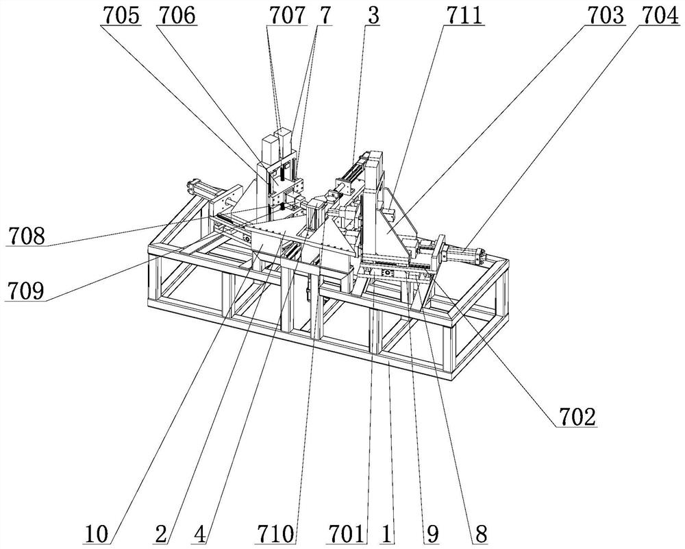
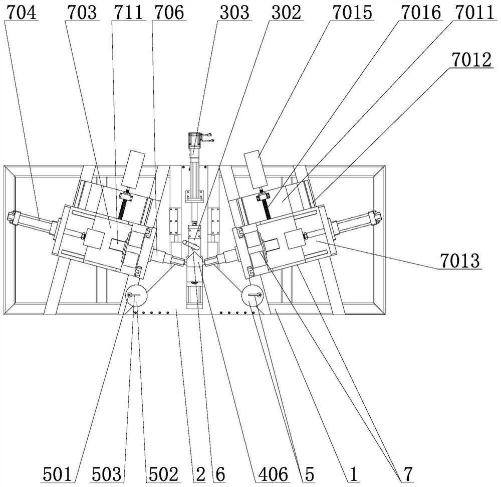
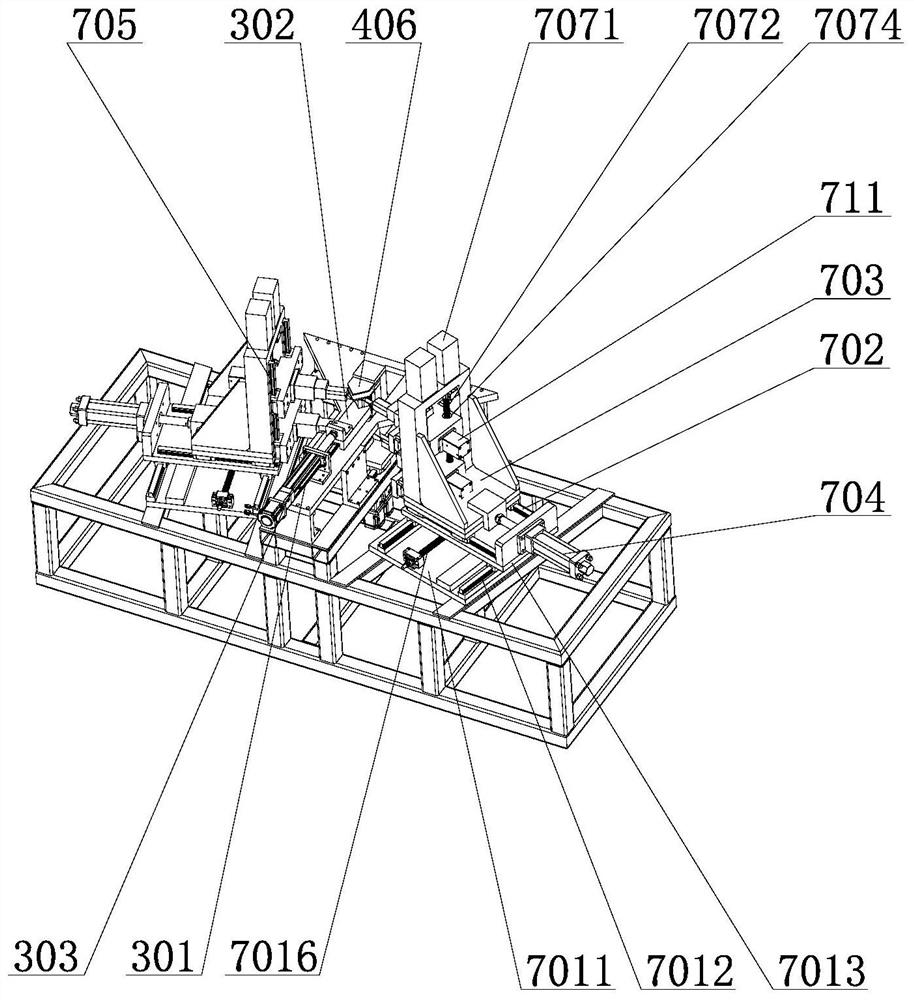
The invention relates to a full-automatic numerical control corner splicing machine and a corner splicing method. The full-automatic numerical control corner splicing machine comprises a rack, a workbench plate is arranged on the rack, an outer corner positioning mechanism, an inner corner positioning mechanism, a vertical pressing mechanism and a side positioning mechanism are arranged on the workbench plate, and two grading corner splicing structures are arranged on the rack; the grading corner splicing structures comprise horizontal adjusting mechanisms, pre-feeding guide rails are arranged on the horizontal adjusting mechanisms, pre-feeding sliding seats are arranged on the pre-feeding guide rails and connected with pre-feeding oil cylinders, vertical adjusting guide rails are arranged on the pre-feeding sliding seats, two vertical adjusting sliding seats are arranged on each vertical adjusting guide rail, the vertical adjusting sliding seats are connected with vertical adjusting mechanisms, the vertical adjusting sliding seats are movably provided with corner splicing tool aprons, corner splicing tools are arranged at the front end of the corner splicing tool aprons, the rear ends of the corner splicing tool aprons are connected with corner splicing oil cylinders, and the corner splicing oil cylinders work in a full-stroke manner. A control system is respectively connected with the outer corner positioning mechanism, the inner corner positioning mechanism and the grading angle splicing structures. The full-automatic numerical control corner splicing machine has the advantages of being reasonable in structural design, high in corner splicing adjusting efficiency, high in corner splicing precision, high in corner splicing efficiency and the like.

Description

Technical field: [0001] The invention relates to the technical field of door and window processing equipment, in particular to a fully automatic numerically controlled angle forming machine and an angle forming method thereof. Background technique: [0002] The corner forming machine is an indispensable processing equipment in the processing of doors and windows, and it is mainly used for the splicing processing of two adjacent profiles. Most of the existing window frames and door frames are spliced ​​by several profiles, for example, most of them are spliced ​​with quadrilaterals. When forming corners, first insert a corner code into two adjacent profiles, then put the two profiles together, and then place the assembled two profiles on the workbench of the corner forming machine to fix them, and then drive the corner knives through hydraulic drive Simultaneously impact the sides of the two profiles, impact the sides of the profiles into the groove of the corner bracket, an...

Claims


Application Information

Patent Timeline
Patent Type & Authority Applications(China)
IPC IPC(8): B25B11/02B25B27/02
CPCB25B11/02B25B27/026
Inventor 王令红
Owner 济南康宏机械有限公司
Learn More