Vehicle-mounted mobile phone wireless charging box

A technology for wireless charging and vehicle-mounted mobile phones, which is applied in the direction of current collectors, electric vehicles, and electrical components. compact effect

Pending Publication Date: 2021-11-30
BEIJING CHANGAN AUTOMOBILE ENG TECH RES
View PDF8 Cites 0 Cited by
  • Summary
  • Abstract
  • Description
  • Claims
  • Application Information

AI Technical Summary

Problems solved by technology

The structure of the whole device is simple, but there are also the following problems: (1) The object to be charged is not fixed, and it is easy to fall over during the movement of the vehicle; (2) The height of the horizontally arranged charging plate is too high, which will cause a mismatch with the device to be charged and cannot Charging problem; (3) The device takes up a lot of space, and the charging device leaks outside, and the appearance is not simple enough
This device has the following problems: (1) The device takes up a lot of space; (2) The magnetic attraction component has no adsorption and fixation effect on some charged equipment; (3) Only a small wireless charging coil can be used, and the compatibility is insufficient

Method used


Image

  • Vehicle-mounted mobile phone wireless charging box
  • Vehicle-mounted mobile phone wireless charging box
  • Vehicle-mounted mobile phone wireless charging box

Examples


Embodiment Construction

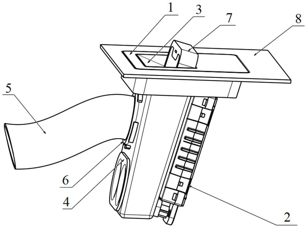
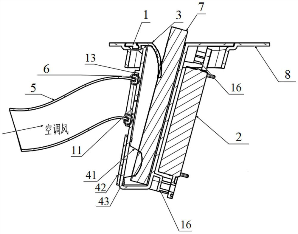
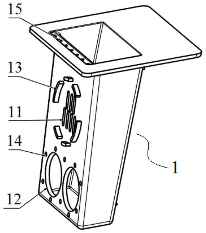
[0025] Such as Figure 1 to Figure 6 The wireless charging box for the vehicle-mounted mobile phone shown includes a box body 1 , a wireless charging module 2 , a rubber stopper 3 , a rubber stopper 4 and an air duct 5 . The upper part of the right side wall of the box body 1 is provided with two screw posts 16 at intervals, the lower part of the right side wall of the box body 1 is provided with a screw post 16, and the three screw posts 16 are provided with screw mounting holes, and the wireless charging module 2 passes through The screw connection of three screws and three screw columns 16 is fixedly mounted on the right side wall of the box body 1 . The lower surface of the left side of the rubber baffle 3 has seven second connecting columns 31 , and the right side of the rubber baffle 3 is provided with sawtooth grooves 32 , forming a zigzag weakened edge. Seven second connecting holes 15 are opened on the top mounting plate of the box body 1, and the seven second connec...


PUM


Abstract

The invention discloses a vehicle-mounted mobile phone wireless charging box which comprises a box body and a wireless charging module installed on the right side wall of the box body. The vehicle-mounted mobile phone wireless charging box further comprises a rubber blocking piece, a rubber limiting piece and an air pipe, wherein the rubber blocking piece is fixedly connected to the top surface of the box body and shields an inner cavity of the box body, and the rubber limiting piece is provided with a limiting bulge; the left side wall of the box body is provided with a ventilation opening, a receding hole and air pipe limiting ribs, the air pipe limiting ribs form a circle and are located on the periphery of the ventilation opening, and the receding hole is located below the air pipe limiting ribs; the rubber limiting piece is fixedly connected to the left side wall of the box body, and the limiting bulge of the rubber limiting piece penetrates through the receding hole to extend into the inner cavity of the box body and can limit a mobile phone placed in the inner cavity of the box body to be charged to move; and one end of the air pipe is fixedly butted with the air pipe limiting rib, the air pipe is communicated with the inner cavity of the box body through the ventilation opening, and the other end of the air pipe can be communicated with an air conditioner air outlet pipeline. The vehicle-mounted mobile phone wireless charging box is compact in structure, safe and practical, and can realize smooth charging of a mobile phone in different environments.

Description

technical field [0001] The invention relates to a vehicle auxiliary device, in particular to a wireless charging box for a vehicle mobile phone. Background technique [0002] With the popularity of smartphones, charging your phone is something you need to do every day. Charging mobile phones is a high-frequency usage scenario for drivers and passengers during driving. [0003] CN211958795U discloses a wireless charging device, which includes two charging magnetic fields, one vertically arranged and one horizontally arranged, wherein the horizontally arranged charging plate is in a foldable form. The structure of the whole device is simple, but there are also the following problems: (1) The object to be charged is not fixed, and it is easy to fall over during the movement of the vehicle; (2) The height of the horizontally arranged charging plate is too high, which will cause a mismatch with the device to be charged and cannot The problem of charging; (3) The device takes up...

Claims


Application Information

Patent Timeline
Patent Type & Authority Applications(China)
IPC IPC(8): H02J50/00H02J50/10H02J7/00H05K5/02H05K7/20B60H1/00
CPCH02J50/005H02J50/10H02J7/0044H05K5/0213H05K7/20909B60H1/00271B60H2001/003
Inventor 郁剑林何洋
Owner BEIJING CHANGAN AUTOMOBILE ENG TECH RES
Why Eureka
Try Eureka