
System for pneumatic conveying of particulate matters and gas supply device

A pneumatic conveying and conveying system technology, which is applied in the direction of conveying bulk materials, conveyors, transportation and packaging, etc., to achieve the effects of slowing down wear, better controlling the pneumatic conveying of particles, and improving adaptability

Pending Publication Date: 2021-11-30
CHENGDU RUIKELIN ENG TECH
View PDF8 Cites 0 Cited by
  • Summary
  • Abstract
  • Description
  • Claims
  • Application Information

AI Technical Summary

Problems solved by technology

[0007] The purpose of the embodiment of the present application is to provide a system, device and method for pneumatic conveying of particulate matter, so as to solve technical problems that help to better control the pneumatic conveying of particulate matter
[0008] Another purpose of the embodiment of the present application is to provide a system and an air supply device for pneumatic conveying of particulate matter, so as to solve the technical problem of conveniently supplying air to the system for pneumatic conveying of particulate matter

Method used


Image

  • System for pneumatic conveying of particulate matters and gas supply device
  • System for pneumatic conveying of particulate matters and gas supply device
  • System for pneumatic conveying of particulate matters and gas supply device

Examples


application approach 1

[0120] Figure 8 It is a schematic structural diagram of a control system of a system for pneumatic conveying of particulate matter according to an embodiment of the present application. The implementation of application scheme 1 can be based on such as Figure 8 control system shown. like Figure 8 As shown, the control system includes a control device 41 and various sensors and actuators connected with the control device 41 by signals.

[0121] like Figure 8 As shown, the control device 41 includes a processor 411 , a memory 412 and a communication interface 415 . The processor 411 and the memory 412 are connected to the communication interface 415, for example, through various interfaces, transmission lines or buses. Optionally, the control device 41 may further include an input device 413 and an output device 414 . Optionally, the control device 41 may adopt a PLC (Programmable Logic Controller) control system.

[0122] The processor 411 may include a central proce...

application approach 2

[0131] In application scheme 2, except that the bulk density of the particulate matter in the silo 11 is less than that of application scheme 1 (the bulk density of the particulate matter in application scheme 2 is 1kg / m 3 ), and the rest of the content is the same as that of application scheme 1.


PUM


Abstract

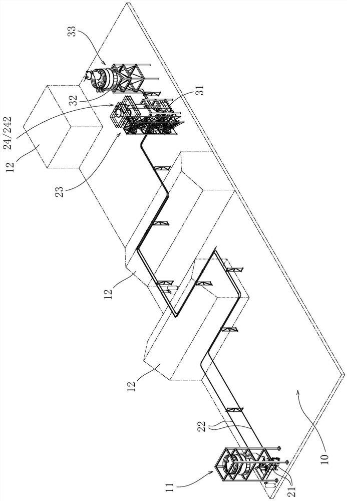
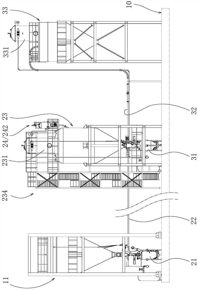
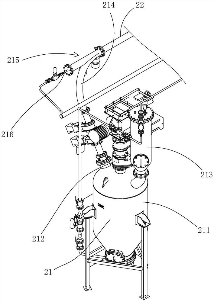
An embodiment of the invention aims at providing a system for pneumatic conveying of particulate matters and a gas supply device so as to achieve the technical purpose of conveniently supplying gas to the system for pneumatic conveying of the particulate matters. The system for pneumatic conveying of the particulate matters comprises a first particulate matter fluidizer for fluidizing to-be-conveyed first particulate matters by the aid of a fluidizing gas so as to generate and output a gas-particulate matter mixed flow, a first particulate matter conveying pipe used for conveying the gas-particulate matter mixed flow output from the first particulate matter fluidizer along a set route, and a first particulate matter recovery bin; the first particulate matter conveying pipe is provided with at least one straight pipe section gas supply node used for providing axial pressure compensation gas flow for the gas-particulate matter mixed flow conveyed by the first particulate matter conveying pipe; each straight pipe section gas supply node supplies gas to a straight pipe section of the first particulate matter conveying pipe through a nozzle which is arranged on the inner wall of the straight pipe section of the first particulate matter conveying pipe and faces the particulate matter conveying direction.

Description

technical field [0001] The embodiment of the present application relates to particle conveying technology, in particular to a system, device and method for pneumatic conveying of particles. Background technique [0002] Pneumatic conveying of particulate matter, as the name implies, refers to the technology of using airflow to push the flow of particulate matter in the pipeline to realize the conveying of particulate matter. A common pneumatic conveying method for particulate matter is to fluidize the particulate matter to be transported by gas to form a gas-particulate mixed flow (commonly known as gas-solid two-phase flow), and then transport the gas-particulate mixed flow to the destination through a pipeline, and , as the gas-particulate mixed flow reaches its destination, the gas brought by the gas-particulate mixed flow will also be automatically drawn out and discharged into the atmosphere. [0003] The key to successful pneumatic conveying of particulate matter is t...

Claims


Application Information

Patent Timeline
Patent Type & Authority Applications(China)
IPC IPC(8): B65G53/16B65G53/60B65G53/52B65G53/58B65G53/66
CPCB65G53/16B65G53/60B65G53/521B65G53/58B65G53/66
Inventor 谭险峰黄涛
Owner CHENGDU RUIKELIN ENG TECH
Learn More