
A Combined Industrial Dust Explosion Simulation Demonstration System

A dust explosion and demonstration system technology, applied in the security field, can solve the problems of inability to reflect the pressure and temperature of dust explosion, inability to visualize the explosion effect, and inability to reflect the movement of dust, etc., to improve portability and disassembly performance, work Stable and reliable performance and quick response

Active Publication Date: 2020-04-28
SHANGHAI RES INST OF CHEM IND +1
View PDF16 Cites 0 Cited by
  • Summary
  • Abstract
  • Description
  • Claims
  • Application Information

AI Technical Summary

Problems solved by technology

[0004] Most of the existing dust explosion experiment demonstration devices adopt steel pipe structure to withstand the maximum pressure generated by the explosion, and cannot achieve a visualized explosion effect; although the existing dust explosion experiment demonstration devices have a visual effect, they generally use airflow disturbance , cause the movement of dust in the pipeline, and the powder spraying method is simple, which cannot reflect the dust movement status under working conditions, nor can it reflect the explosion situation in the dust collection state; the existing dust explosion experiment demonstration device does not monitor the pressure and temperature. It cannot reflect the pressure and temperature generated after the dust explosion; the ignition method of the existing dust explosion experiment demonstration device usually uses an open flame as the ignition source, which cannot reflect the common ignition sources such as static electricity, open flame, circuit short circuit, and hot surface under working conditions situation

Method used


Image

  • A Combined Industrial Dust Explosion Simulation Demonstration System
  • A Combined Industrial Dust Explosion Simulation Demonstration System

Examples


Embodiment

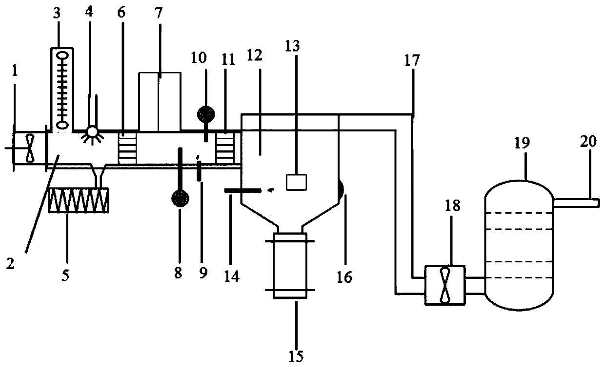
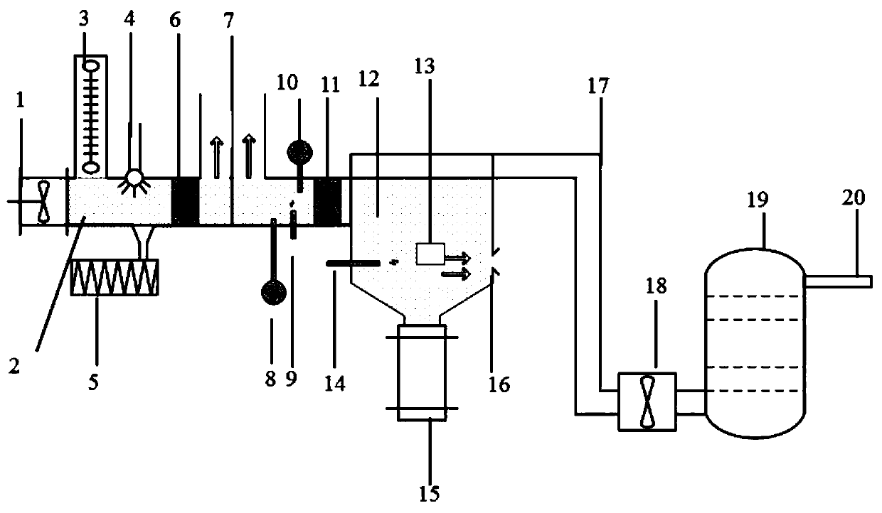
[0031] Such as Figure 1-2 As shown, a combined industrial dust explosion simulation demonstration system includes a dust explosion reaction observation pipe 2, a frequency conversion axial flow fan 1 arranged at one end of the dust explosion reaction observation pipe 2, and is arranged at the other end of the dust explosion reaction observation pipe 2 and connected to the dust explosion reaction observation pipe 2. The dust collector 12 connected to the dust explosion reaction observation pipe 2, the dust conveying unit located between the frequency conversion axial flow fan 1 and the dust collector 12 and connected to the dust explosion reaction observation pipe 2, set in the dust explosion reaction observation pipe 2 The ignition detection control unit on the top, the dust collection box 15 arranged at the bottom of the dust collector 12, the clean air pipeline 17 connected with the top of the dust collector 12, the exhaust gas purifier 19 connected with the clean air pipeli...


PUM


Abstract

The invention relates to a combined type industrial dust explosion simulation demonstration system which comprises a dust explosion reaction observation pipeline, a variable frequency axial flow fan arranged at one end of the dust explosion reaction observation pipeline, a dust collector arranged at the other end of the dust explosion reaction observation pipeline and communicated with the dust explosion reaction observation pipeline, a dust conveying unit located between the variable frequency axial flow fan and the dust collector and communicated with the dust explosion reaction observation pipeline, an ignition detection control unit arranged on the dust explosion reaction observation pipeline, a dust collection box arranged at the bottom of the dust collector, a purified air pipeline communicated with the top of the dust collector, as well as a tail gas purifier and an electronic controller that are communicated with the purified air pipeline. Compared with the prior art, the system disclosed by the invention is maintained easily, is suitable for various conditions, has the characteristics of being carried conveniently, being simple in operation, good in an explosion display effect and high in cost performance and the like, and can be used for a dust explosion test and a practical training demonstration at any time everywhere.

Description

technical field [0001] The invention belongs to the technical field of safety and relates to a combined industrial dust explosion simulation demonstration system. Background technique [0002] In recent years, frequent dust explosion accidents have caused heavy casualties and property losses. According to the cause of the accident, dust explosion accidents mostly occur in the dust conveying pipeline system and the dust collection and exhaust pipeline system. The dust conveying pipeline system is one of the essential processes in the powder-related production process, which has the advantages of saving manpower, high conveying efficiency, and occupying less resources. Among these dust conveying pipeline systems, especially the scraper powder conveying system, pneumatic powder conveying system and screw powder conveying device are the most widely used. These powder conveying systems are usually combined with multiple devices according to the needs of production. The pneumat...

Claims


Application Information

Patent Timeline
Patent Type & Authority Patents(China)
IPC IPC(8): G01N25/54
CPCG01N25/54
Inventor 曾国良张小沁肖秋平周健缪晓栋王耀蔡晨仁沈思思盛夏
Owner SHANGHAI RES INST OF CHEM IND
Learn More