
Cage type slag crusher

A slag crusher and cage type technology, which is applied in the field of slag particle refinement equipment, can solve the problems of user intimidation, transportation difficulties, high operating costs, etc., and achieves the effect of reasonable structure, convenient manufacture and use, and pneumatic conveying.

Inactive Publication Date: 2005-11-09
陈春梅
View PDF0 Cites 0 Cited by
  • Summary
  • Abstract
  • Description
  • Claims
  • Application Information

AI Technical Summary

Problems solved by technology

[0002] Pneumatic conveying of bulk materials is increasingly common in boiler ash and slag conveying, but there are great difficulties in pneumatically conveying fluidized bed boiler bottom slag
Because the bottom slag particles of fluidized bed boilers are relatively large, it is difficult to transport; large particles need high-speed air flow to transport, and the high operating costs caused by the severe wear and tear of pipelines and valves accompanying high-speed transport often deter users.

Method used


Image

  • Cage type slag crusher
  • Cage type slag crusher
  • Cage type slag crusher

Examples


specific Embodiment approach

[0016] (5) Specific implementation methods, combined with accompanying drawings

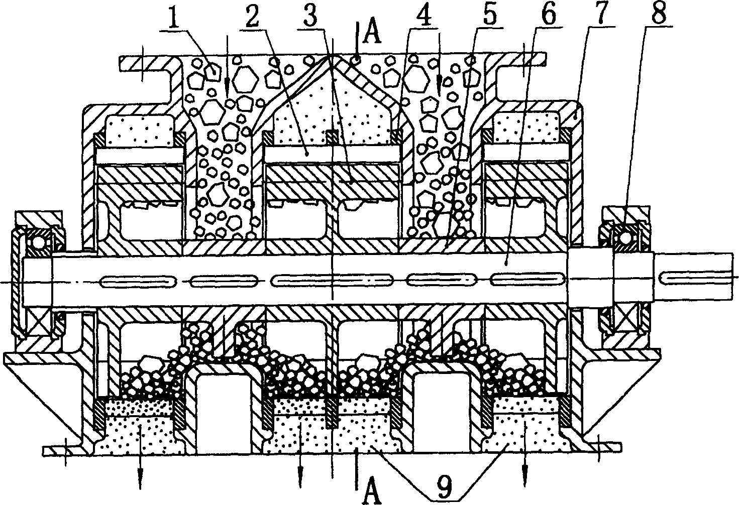
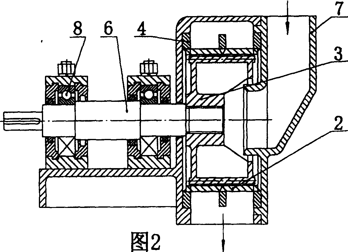
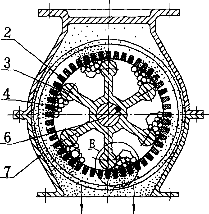
[0017] figure 1 It is a structural schematic diagram of a cage-type slag crusher including 3 sets of impellers and a stator. The cage-type slag crusher includes a housing 7, and a stator composed of an annular skeleton 4 inlaid with grid bars 2 is fixedly installed in the housing 7. The section of the grid bar 2 is trapezoidal. The rotor that can rotate at a high speed is housed in the stator is formed by the impeller 3 sleeved on the main shaft 6 of the slag crusher, and the main shaft of the slag crusher is supported by bearings 8 . The cross section of the impeller 3 is slightly like a chrysanthemum, and the 6 petals are evenly distributed along the circumference, and the ends of the petals are arc-shaped. image 3 As can be seen. There are 3 sets of stators and impellers, and two spacers 5 are arranged between the 3 sets of impellers mounted on the main shaft.

[0018] Fig. 2 shows anothe...


PUM


Abstract

A cage-type cinder breaker for fluidized-bed boiler is composed of casing, stator consisting of ring skeleton and fine bars inlaid in said ring skeleton, and high-speed rotor, which is in said stator and consists of daisy wheel and mainshaft supported by bearings.

Description

(1) Technical field [0001] The invention relates to a slag particle refinement equipment required for pneumatic conveying of the bottom slag of a fluidized bed boiler, in particular to a cage type slag crusher. (2) Background technology [0002] Pneumatic conveying of bulk materials is widely used in conveying boiler ash and slag, but there are great difficulties in pneumatically conveying fluidized bed boiler bottom slag. Because the bottom slag particles of fluidized bed boilers are relatively large, it is difficult to transport them; large particles need high-speed air flow to transport, and the high operating costs caused by the severe wear and tear of pipelines and valves accompanying high-speed transport often deter users. However, the pneumatic conveying of fluidized bed boiler bottom slag is the direction, and the urgent need to solve is the slag particle refinement. (3) Contents of the invention [0003] The purpose of the present invention is to solve the above ...

Claims


Application Information

Patent Timeline
Patent Type & Authority Patents(China)
IPC IPC(8): F23C10/24
Inventor 陈春梅
Owner 陈春梅
Learn More