
Manufacturing method of kettle

A manufacturing method and spout technology, applied to household containers, etc., can solve problems such as weld damage, vacuum layer failure, and tiny gaps

Active Publication Date: 2021-11-30
ZHEJIANG FEIJIAN IND & TRADE
View PDF13 Cites 4 Cited by
  • Summary
  • Abstract
  • Description
  • Claims
  • Application Information

AI Technical Summary

Problems solved by technology

[0003] The present invention aims at the processing of the spout in the prior art, which may lead to wire drawing on the inner surface of the inner tank, which may cause damage to the welded part of the inner tank and the outer shell or produce tiny gaps, resulting in the failure of the vacuum layer or the use of vacuum insulation. Defects such as shortened lifespan provide a new manufacturing method for pots

Method used


Image

  • Manufacturing method of kettle
  • Manufacturing method of kettle
  • Manufacturing method of kettle

Examples


Embodiment 1

[0061] A method for making a pot, comprising the steps of:

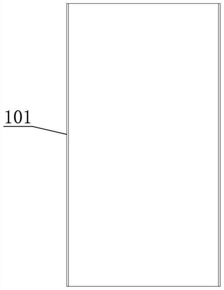
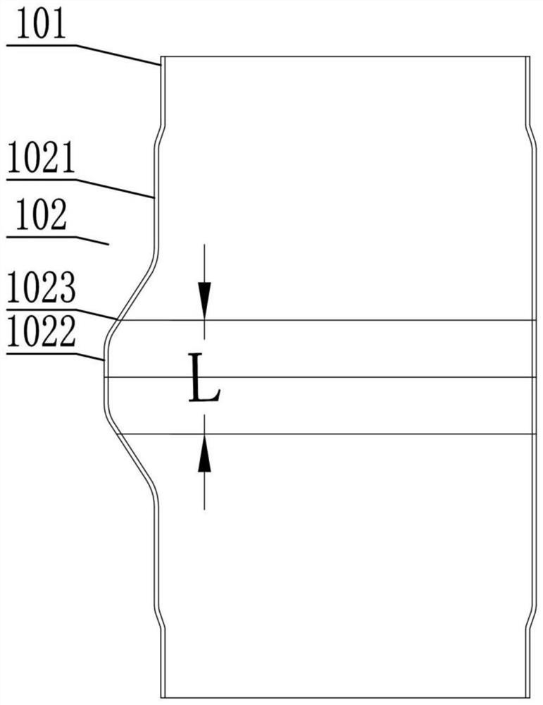
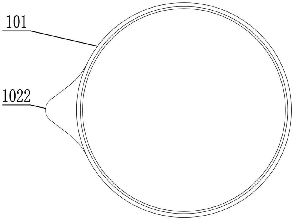
[0062] a. Take a pipe 101 and carry out surface pretreatment. After the surface pretreatment is completed, the pipe 101 is swelled and formed in the middle of the pipe 101 with an outer convex portion 102. The outer convex portion 102 includes a processing area 1021, A margin area 1022, the margin area 1022 is located in the middle of the convex portion 102, the processing area 1021 is located on both sides of the convex portion 102, the thickness of the pipe 101 is 1mm, the margin The length L of the zone 1022 is 22mm;

[0063] b. Laser cut the pipe material 101 from the middle of the margin area 1022 to obtain a spout body 103 with a small convex portion 104, and then shape the small convex portion 104 to make the small convex portion 104 Retract toward the direction of the pipe material 101, and then laser cut the small convex portion 104 again, so as to form the spout 105 on the spout body 103;

[0064] c. Cut ...

Embodiment 2

[0074] A method for making a pot, comprising the steps of:

[0075] a. Take a pipe 101 and carry out surface pretreatment. After the surface pretreatment is completed, the pipe 101 is swelled and formed in the middle of the pipe 101 with an outer convex portion 102. The outer convex portion 102 includes a processing area 1021, A margin area 1022, the margin area 1022 is located in the middle of the convex portion 102, the processing area 1021 is located on both sides of the convex portion 102, the thickness of the pipe 101 is 1.5 mm, and the margin The length L of the measuring area 1022 is 30mm;

[0076] b. Laser cut the pipe material 101 from the middle of the margin area 1022 to obtain a spout body 103 with a small convex portion 104, and then shape the small convex portion 104 to make the small convex portion 104 Retract toward the direction of the pipe material 101, and then laser cut the small convex portion 104 again, so as to form the spout 105 on the spout body 103; ...

Embodiment 3

[0087] A method for making a pot, comprising the steps of:

[0088] a. Take a pipe 101 and carry out surface pretreatment. After the surface pretreatment is completed, the pipe 101 is swelled and formed in the middle of the pipe 101 with an outer convex portion 102. The outer convex portion 102 includes a processing area 1021, A margin area 1022, the margin area 1022 is located in the middle of the convex portion 102, the processing area 1021 is located on both sides of the convex portion 102, the thickness of the pipe 101 is 1.2mm, and the excess The length L of the measuring area 1022 is 26mm;

[0089] b. Laser cut the pipe material 101 from the middle of the margin area 1022 to obtain a spout body 103 with a small convex portion 104, and then shape the small convex portion 104 to make the small convex portion 104 Retract toward the direction of the pipe material 101, and then laser cut the small convex portion 104 again, so as to form the spout 105 on the spout body 103; ...


PUM

PropertyMeasurementUnit
thicknessaaaaaaaaaa
lengthaaaaaaaaaa
thicknessaaaaaaaaaa

Abstract

The invention discloses a manufacturing method of a kettle. The manufacturing method comprises the following steps of: a, taking a pipe for water swelling; b, cutting to obtain a kettle mouth blank with a small convex part, then shaping, and cutting again to form a kettle mouth; c, cutting the kettle mouth blank to obtain a kettle mouth connecting body, and then turning a connecting step; d, taking an inner container, aligning the kettle mouth connecting body with the inner container, and then welding; e, taking a shell, aligning the shell with the connecting step, and then welding; f, taking a shell bottom, aligning the shell bottom with the shell, and then welding to obtain a kettle body semi-finished product; g, carrying out vacuumizing operation to form a vacuum layer; and h, taking a handle, and connecting the handle with the shell and the kettle mouth connecting body to complete the manufacturing of the kettle. Through the steps, when the kettle with the kettle mouth is manufactured, scratches such as drawing wires cannot be formed on the surface of the kettle mouth, the deformation of the inner container and the shell cannot be caused, and the welding position of the inner container and the shell cannot be damaged, so that the kettle mouth with a smooth surface can be obtained, and the heat preservation effect of the obtained kettle can be guaranteed.

Description

technical field [0001] The present invention relates to a pot, in particular to a method for making a pot. Background technique [0002] At present, when the kettle with the spout is manufactured, the inner container and the outer shell are generally manufactured earlier, and the inner container and the outer shell are welded and then evacuated to obtain a vacuum layer, and finally the spout is processed at the mouth of the pot. Although the manufacturing method of this kind of pot can obtain a pot with a spout, in the process of processing the spout, the spout is obtained by pressing out the shape of the spout from the inside of the inner tank. Drawing occurs on the inner surface of the liner, destroying the appearance of the liner. On the other hand, in the process of deforming the mouth of the inner tank and the outer shell into a spout, the welds of the inner tank and the outer shell may be damaged or produce tiny gaps, which will lead to failure of the vacuum layer or ...

Claims


Application Information

Patent Timeline
Patent Type & Authority Applications(China)
IPC IPC(8): B23P15/00A47G19/12
CPCB23P15/00A47G19/12A47G19/127
Inventor 赵洪杨道海王华波杨厚华杨品
Owner ZHEJIANG FEIJIAN IND & TRADE
Learn More