
Hydrogen fuel cell tail gas mixing and diluting device and hydrogen fuel cell

A fuel cell and exhaust gas mixing technology, which is applied in the direction of fuel cells, mixers, mixing methods, etc., can solve the problems of uneven gas composition and unguaranteed safety, and achieve hydrogen dilution and uniform mixing with good safety performance , the effect of improving safety

Pending Publication Date: 2021-11-30
FAW JIEFANG AUTOMOTIVE CO
View PDF0 Cites 0 Cited by
  • Summary
  • Abstract
  • Description
  • Claims
  • Application Information

AI Technical Summary

Problems solved by technology

Although the dilution device in the prior art can dilute hydrogen, the composition of the diluted gas is not uniform, and the safety cannot be guaranteed.

Method used


Image

  • Hydrogen fuel cell tail gas mixing and diluting device and hydrogen fuel cell
  • Hydrogen fuel cell tail gas mixing and diluting device and hydrogen fuel cell
  • Hydrogen fuel cell tail gas mixing and diluting device and hydrogen fuel cell

Examples


Embodiment 1

[0038] Hydrogen fuel cells have the advantages of no pollution, high reactant preparation efficiency, and are conducive to improving the NVH performance of automobiles, and have excellent application prospects. However, because the existing hydrogen exhaust system cannot guarantee sufficient dilution of hydrogen, this embodiment provides a hydrogen fuel cell exhaust gas mixing and dilution device to solve this problem.

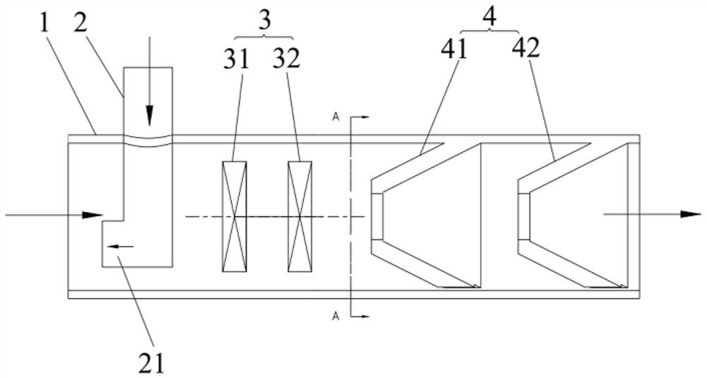
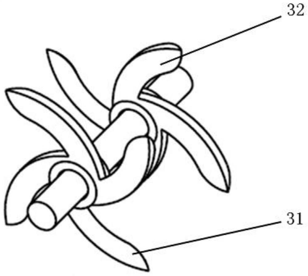
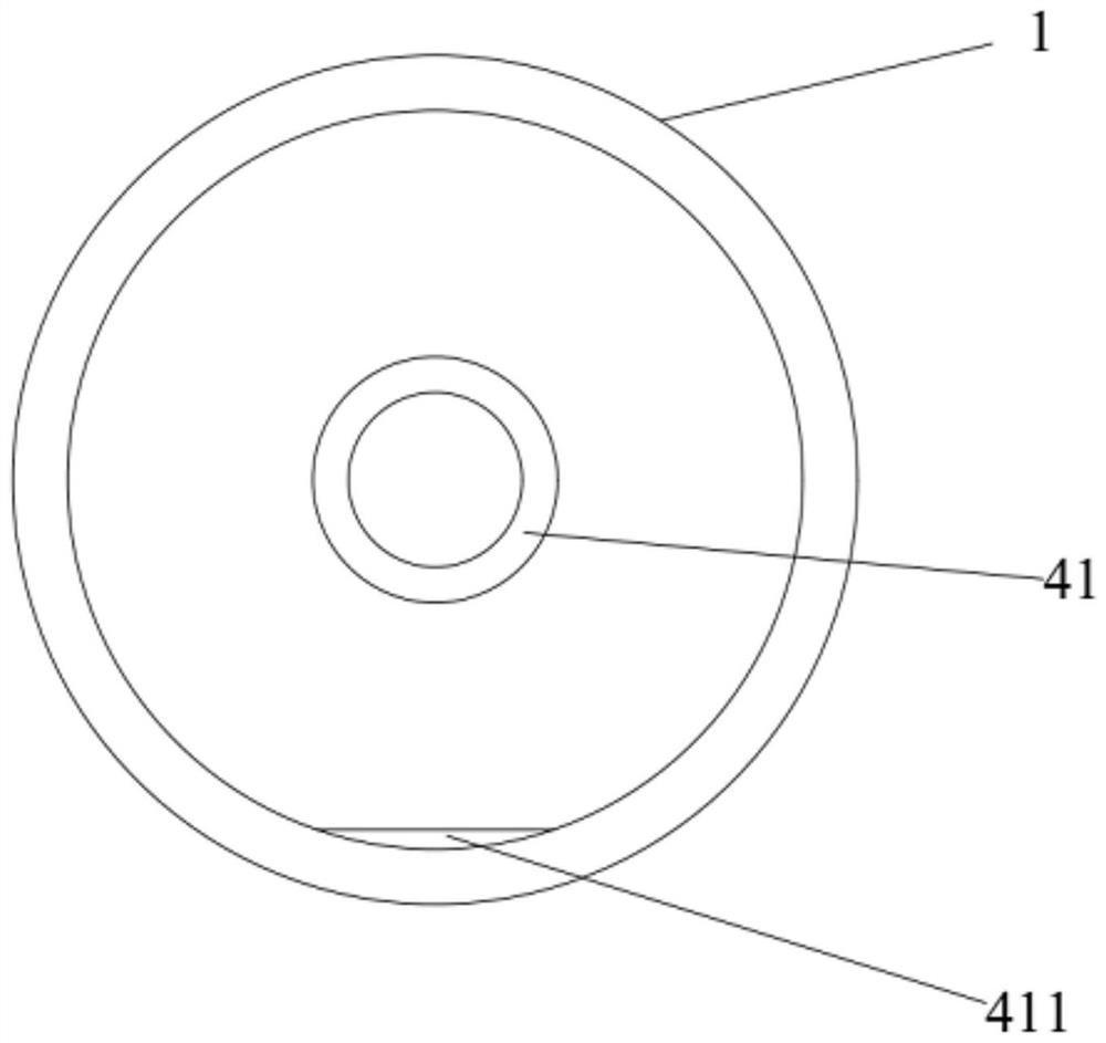
[0039] like figure 1 As shown, the hydrogen fuel cell exhaust gas mixing and dilution device includes a main exhaust pipe 1 and a hydrogen exhaust pipe 2 . After the fuel in the hydrogen fuel cell system undergoes a stack reaction, the tail gas includes hydrogen and air. Wherein, the air is discharged from the main tail pipe 1, and the hydrogen is discharged from the hydrogen tail pipe 2. In the stack reaction, the ratio of hydrogen to oxygen is 2:1, but in order to ensure the utilization rate of hydrogen, an oversupply of air is adopted in the actual supply...

Embodiment 2

[0048] This embodiment provides a hydrogen fuel cell, including the hydrogen fuel cell tail gas mixing and dilution device in Embodiment 1. The hydrogen fuel cell is equipped with the hydrogen fuel cell tail gas mixing and dilution device in the first embodiment, which can realize the dilution and uniform mixing of the tail gas hydrogen, so as to have good safety performance.

[0049] Specifically, the hydrogen fuel cell exhaust gas mixing and dilution device is installed obliquely in the hydrogen fuel cell, and it is necessary to ensure that the value range of the angle α between the main exhaust pipe 1 and the horizontal plane is 5°<α≤90°, that is, for To ensure that the condensed water is discharged in time, α needs to be greater than 5°. The upstream of the main tailpipe 1 and the hydrogen tailpipe 2 in the hydrogen fuel cell tail gas mixing and dilution device are connected to the stack reactor, and the fuel of the hydrogen fuel cell is hydrogen after the stack reaction. ...


PUM


Abstract

The invention relates to the technical field of automobiles, in particular to a hydrogen fuel cell tail gas mixing and diluting device which comprises a main tail gas exhaust pipeline, a hydrogen tail gas exhaust pipeline, a mixing device and a silencing device. A mounting hole is formed in the main tail exhaust pipeline, air circulates in the main tail exhaust pipeline, hydrogen circulates in the hydrogen tail exhaust pipeline, the hydrogen tail exhaust pipeline penetrates through the mounting hole so that a hydrogen outlet of the hydrogen tail exhaust pipeline can be formed in the main tail exhaust pipeline, and the mixing device is arranged in the main tail exhaust pipeline and located on the downstream of the hydrogen outlet. The mixing device is used for uniformly mixing air and hydrogen, and the silencing device is arranged in the main tail exhaust pipeline, is positioned at the downstream of the mixing device and is used for reducing noise in the main tail exhaust pipeline. The hydrogen fuel cell tail gas mixing and diluting device can ensure that hydrogen is diluted and uniformly mixed, so that the safety of a hydrogen fuel cell is improved. The invention further provides a hydrogen fuel cell which comprises the hydrogen fuel cell tail gas mixing and diluting device.

Description

technical field [0001] The invention relates to the technical field of automobiles, in particular to a hydrogen fuel cell exhaust gas mixing and dilution device and a hydrogen fuel cell. Background technique [0002] Fuel cell technology is a technology that directly converts the chemical energy of fuel into electrical energy through chemical reactions. A hydrogen fuel cell is a power generation device that directly converts the chemical energy of hydrogen and oxygen into electrical energy. The application of hydrogen fuel cells in the automotive field has many advantages. First, there is no noise from traditional mechanical transmission during the reaction process, which is conducive to improving the NVH (Noise Vibration Harshness, Noise Vibration Harshness) performance of the car. Not only that, the reactant of the hydrogen fuel cell is only liquid water, the reaction efficiency is high, it is not limited by the Carnot cycle, and it has outstanding advantages in environme...

Claims


Application Information

Patent Timeline
IPC IPC(8): B01F3/02B01F7/04G10K11/16H01M8/0662H01M8/22B01F23/10
CPCH01M8/0662H01M8/22G10K11/161Y02E60/50
Inventor 李克强徐世龙丁成易正根倪永成梅赟栋陈雷雷刘静
Owner FAW JIEFANG AUTOMOTIVE CO
Learn More