
Gas ultrasonic flowmeter

An ultrasonic flowmeter and gas technology, which is applied in the directions of liquid/fluid solid measurement, volume measurement, flow/mass flow measurement, etc., can solve the problem of increasing installation space requirements of the gas ultrasonic flow metering system, and achieve the effect of reducing the impact force

Active Publication Date: 2021-11-26
上海中核维思仪器仪表股份有限公司
View PDF9 Cites 2 Cited by
  • Summary
  • Abstract
  • Description
  • Claims
  • Application Information

AI Technical Summary

Problems solved by technology

[0007] However, this has resulted in an increase in the installation space requirements of the gas ultrasonic flow metering system, that is, when installing the gas ultrasonic flow metering system, a large space must be reserved on the gas pipeline system to meet the requirements of the existing gas flow metering system. The installation of the large-volume metering box equipped during the installation of the ultrasonic flow metering system. This large-volume metering box is used to install the front and rear straight pipe sections, pre-rectifiers, and even noise reduction devices for these auxiliary gas ultrasonic flowmeters.

Method used


Image

  • Gas ultrasonic flowmeter
  • Gas ultrasonic flowmeter
  • Gas ultrasonic flowmeter

Examples


Embodiment

[0081] This embodiment provides a gas ultrasonic flowmeter installed on a gas pipeline for flow detection of gas.

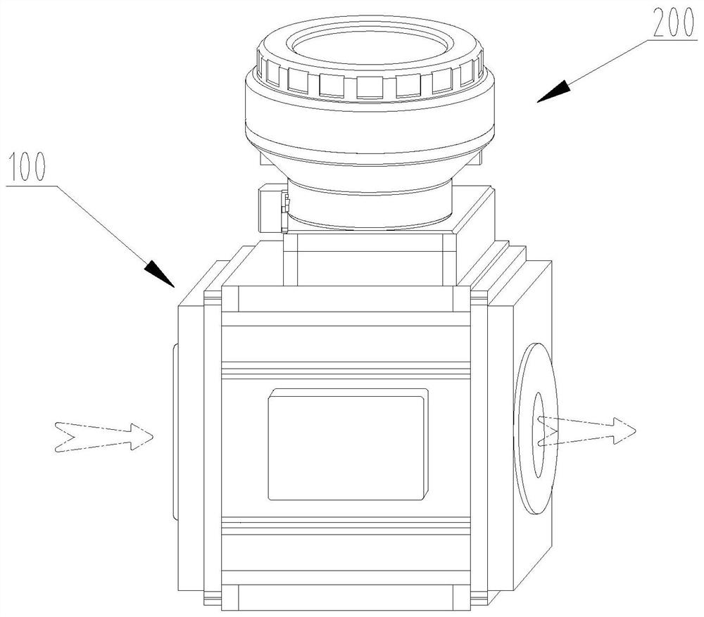
[0082] Such as figure 1 A schematic diagram of a three-dimensional structure of a gas ultrasonic flowmeter provided in an embodiment of the present invention is as follows:

[0083] A gas ultrasonic flowmeter installed on a gas pipeline (not shown in the figure) for flow detection of gas, including a meter body 100, a detection device installed on the meter body 100, the detection device includes a An ultrasonic transducer pair 160 (not shown in the figure) composed of the first ultrasonic transducer 161 and the second ultrasonic transducer 162 for gas flow information.

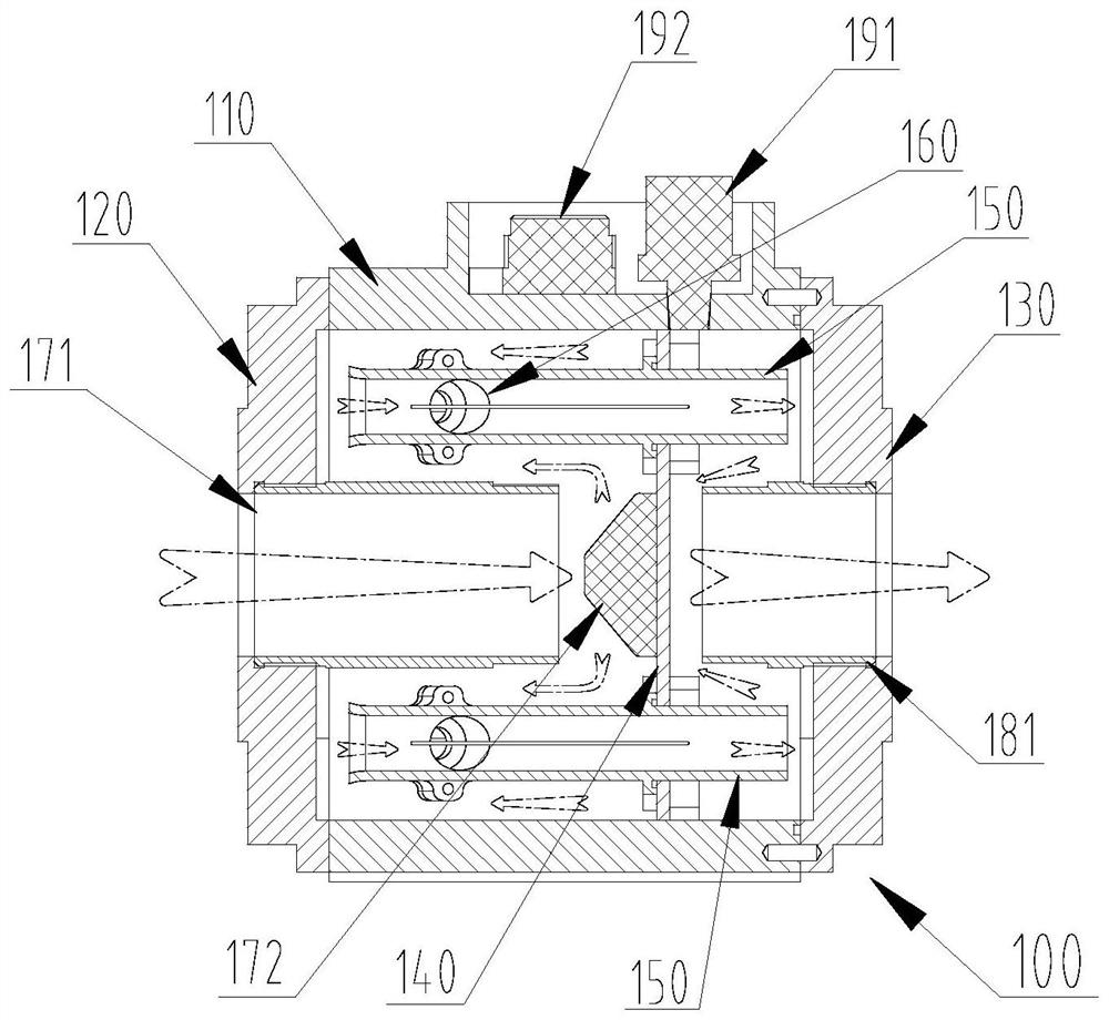
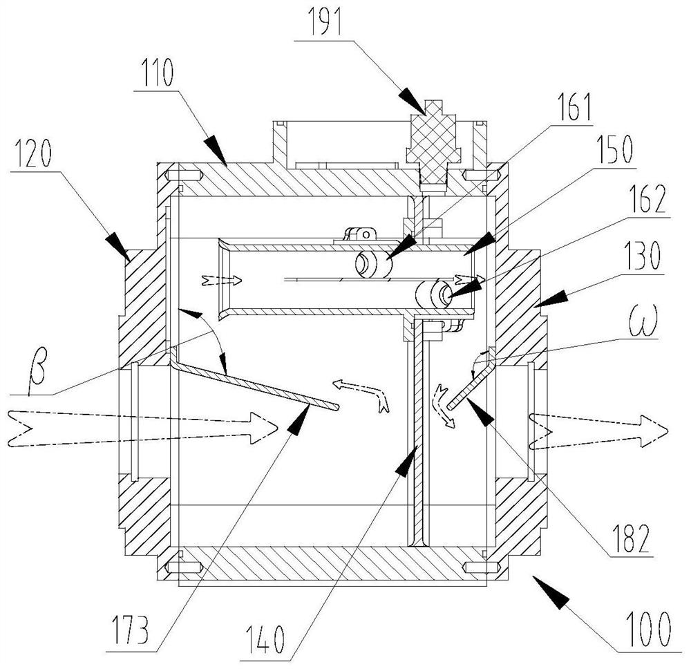
[0084] Such as figure 2 A schematic cross-sectional structural view of the meter body of a gas ultrasonic flowmeter provided by an embodiment of the present invention, image 3 Another kind of gas ultrasonic flowmeter provided by the embodiment of the present invention has a schematic cross-...


PUM


Abstract

The invention discloses a gas ultrasonic flowmeter. A meter body of the gas ultrasonic flowmeter comprises a box body, a front end flange cover with a gas inlet and a rear end flange cover with a gas outlet, one side of the front end flange cover is connected to one end face of the box body, and a gas inlet flow dividing assembly is further arranged in the position, located on the side, of the box body. One side of the rear end flange cover is connected to the other end face of the box body and provided with a gas leading-out component, a partition plate dividing the box body into a gas inlet cavity and a gas outlet cavity is arranged in the box body and located between the gas inlet flow dividing assembly and the gas leading-out component, a hollow measuring pipe section is installed on the partition plate, and the gas inlet end of the measuring pipe section is located in the gas inlet cavity. The gas outlet end of the measuring pipe section is located in the gas outlet cavity, and an ultrasonic transducer pair is installed on the measuring pipe section and used for detecting the flow of gas. A front straight pipe section, a rear straight pipe section and a front flow stabilizer in the prior art are removed, the size of the meter body is effectively reduced, the structure is more compact, installation is more convenient, and the installation requirement of the gas ultrasonic flowmeter in the available space limited area can be met.

Description

technical field [0001] The invention relates to a flow meter, in particular to a gas ultrasonic flow meter, and belongs to the technical field of manufacturing of measuring instruments. Background technique [0002] Gas ultrasonic flowmeter, also known as gas ultrasonic flowmeter, English name: Ubtrasonic gas fbowmeter, is a process control instrument that uses the principle of ultrasonic velocity difference method to detect and measure gas flow. [0003] The gas ultrasonic flowmeter has the characteristics of high accuracy, wide measurement range, and no flow resistance parts. It can measure the two-way flow of gas, including the measurement of steady-state and low-frequency pulsating air flow. It is suitable for various pipe diameters, and The change of gas temperature and pressure in the pipeline can be effectively corrected by the flow computer. [0004] Gas ultrasonic flowmeter is mainly used for flow measurement of various gases, including natural gas, coal gas, coke ...

Claims


Application Information

Patent Timeline
Patent Type & Authority Applications(China)
IPC IPC(8): G01F1/66G01F15/14
CPCG01F1/662G01F15/14
Inventor 罗健忠何胜利石泓然李巧英
Owner 上海中核维思仪器仪表股份有限公司
Learn More