
Forming equipment for machining of automobile skylight guide rails

A technology of guide rail processing and forming equipment, which is applied to other manufacturing equipment/tools, manufacturing tools, etc., can solve the problems of increasing processing costs, inability to ensure accurate positional relationship, strong manual dependence, etc., to achieve enhanced locking and improved drilling The effect of precision

Active Publication Date: 2021-11-26
宁波昌余精铝有限公司
View PDF11 Cites 1 Cited by
  • Summary
  • Abstract
  • Description
  • Claims
  • Application Information

AI Technical Summary

Problems solved by technology

[0004] However, the above-mentioned processing methods mainly have the following defects: 1. Each process is independent of each other, and the transfer of profiles between each process requires manual intervention, there is a risk of missing processes, and the accuracy of the positional relationship cannot be guaranteed, and it is difficult to guarantee the accuracy of the processing size. High scrap rate; 2. Strong dependence on labor, low degree of automation, low production efficiency, prolonging the processing cycle of products and increasing processing costs

Method used


Image

  • Forming equipment for machining of automobile skylight guide rails
  • Forming equipment for machining of automobile skylight guide rails
  • Forming equipment for machining of automobile skylight guide rails

Examples


Embodiment Construction

[0044] Hereinafter, the present application will be further described in conjunction with specific implementation methods. It should be noted that, on the premise of not conflicting, the various embodiments or technical features described below can be combined arbitrarily to form new embodiments.

[0045] In the description of this application, it should be noted that for orientation words, such as the terms "center", "horizontal", "longitudinal", "length", "width", "thickness", "upper", "lower" , "Front", "Back", "Left", "Right", "Vertical", "Horizontal", "Top", "Bottom", "Inner", "Outer", "Clockwise", "Counterclockwise ” and other indication orientations and positional relationships are based on the orientations or positional relationships shown in the drawings, which are only for the convenience of describing the application and simplifying the description, rather than indicating or implying that the device or element referred to must have a specific orientation, use a speci...


PUM


Abstract

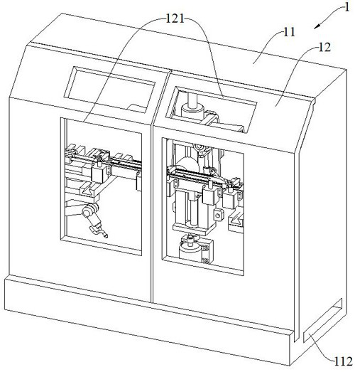
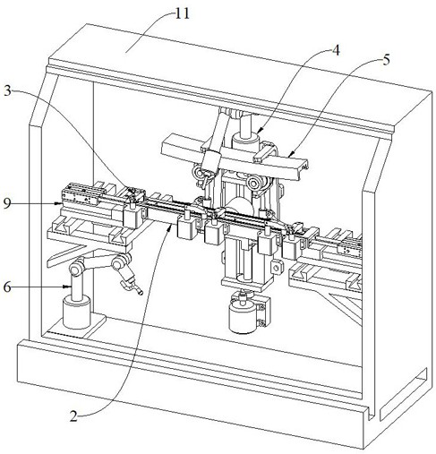
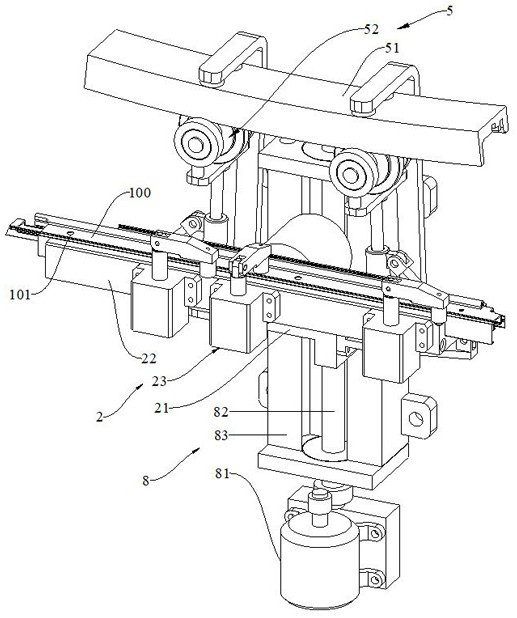
The invention discloses forming equipment for machining of automobile skylight guide rails. The forming equipment comprises a case, a positioning mechanism, a clamping mechanism, a punching mechanism, a milling mechanism and a bending mechanism; the positioning mechanism comprises a mounting frame, a positioning plate and pressing pieces, and the mounting frame is arranged in the case in an up-down sliding manner; the positioning plate is rotatably arranged on the mounting frame, the rotating axis of the positioning plate is arranged in the front-back direction, and a positioning groove with the length smaller than that of a profile is formed in the positioning plate; the pressing pieces are arranged on the positioning plate and used for pressing the profile in the positioning groove; the clamping mechanism comprises two clamping blocks, the two clamping blocks are arranged in the case in a left-right sliding and front-back sliding manner, and the two clamping blocks are located on the left side and the right side of the positioning plate respectively; and the punching mechanism, the milling mechanism and the bending mechanism are all arranged in the case, and the bending mechanism is located on the rear side of the positioning plate. The forming equipment is high in automation degree, easy and convenient to control, high in production efficiency, short in machining period, low in machining cost and low in rejection rate.

Description

technical field [0001] The application relates to the technical field of mechanical processing equipment, in particular to an automobile sunroof guide rail processing and forming equipment. Background technique [0002] The car sunroof is installed on the roof of the car, which can effectively circulate the air in the car, increase the entry of fresh air, and bring health and comfort to the car owner. At the same time, the car window can also broaden the field of vision, and is also commonly used for mobile photography shooting needs . The sunroof guide rail is one of the important parts of the car sunroof, and generally needs to be processed through multiple processes before it can be formed. [0003] In the prior art, the processing method of the automobile sunroof guide rail generally includes the following steps: first transport the cut aluminum alloy profile to the punching station for punching, and then transport the punched profile to the milling station to process t...

Claims


Application Information

Patent Timeline
Patent Type & Authority Applications(China)
IPC IPC(8): B23P23/04
CPCB23P23/04
Inventor 石洪武苟嵩刘术煌刘健
Owner 宁波昌余精铝有限公司
Learn More