Pipeline automatic welding equipment and welding method

An automatic welding and equipment technology, which is applied in welding equipment, auxiliary welding equipment, welding/cutting auxiliary equipment, etc., can solve the problems that the butt tightness of two square steel pipes cannot be guaranteed, the burden on the staff is increased, and the welding effect is not good. , to achieve the effect of improving the welding effect, good welding effect and reducing the possibility of fracture

Active Publication Date: 2021-12-24
江苏德邦流体控制有限公司
View PDF6 Cites 0 Cited by
  • Summary
  • Abstract
  • Description
  • Claims
  • Application Information

AI Technical Summary

Problems solved by technology

[0003] At present, when welding square steel pipes, there are usually the following defects: 1. The traditional butt welding machine needs to clamp and butt two square steel pipes first, and then weld the butt joints. The tightness of the butt joint of the steel pipe cannot be guaranteed, which will lead to poor welding effect and increase the possibility of fracture at the weld during use; 2. The general butt welding method requires manual hand-held welding equipment after two square steel pipes are butt jointed Welding the welding place, this welding method is inefficient, and needs to constantly move the pipes to make them butt joints, which increases the burden on the staff

Method used


Image

  • Pipeline automatic welding equipment and welding method
  • Pipeline automatic welding equipment and welding method
  • Pipeline automatic welding equipment and welding method

Examples


Embodiment Construction

[0031] The embodiments of the present invention will be described in detail below with reference to the accompanying drawings, but the present invention can be implemented in many different ways defined and covered by the claims.

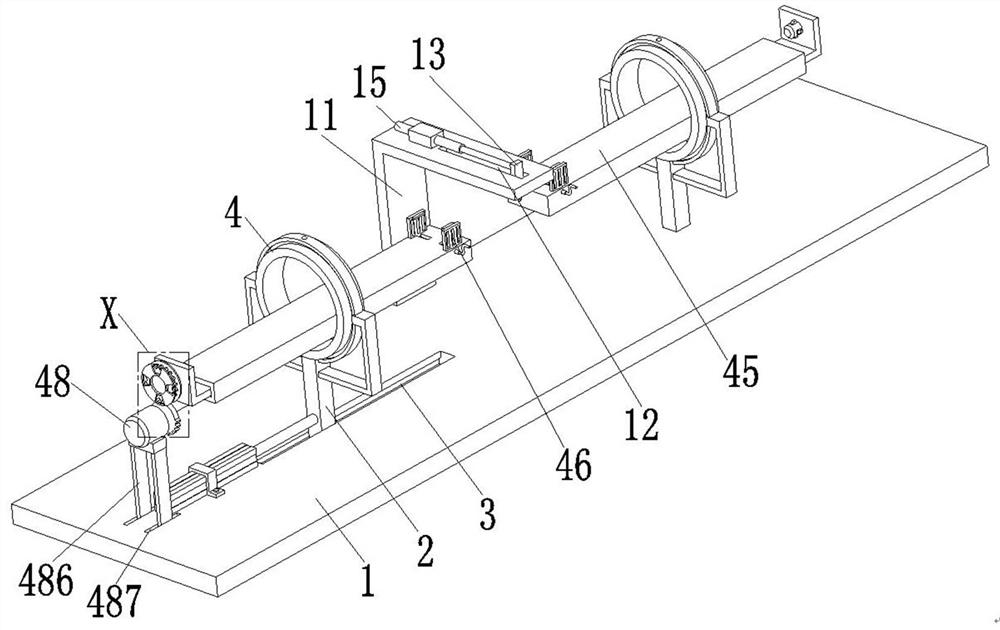
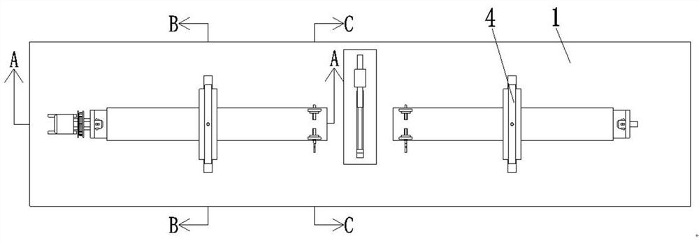
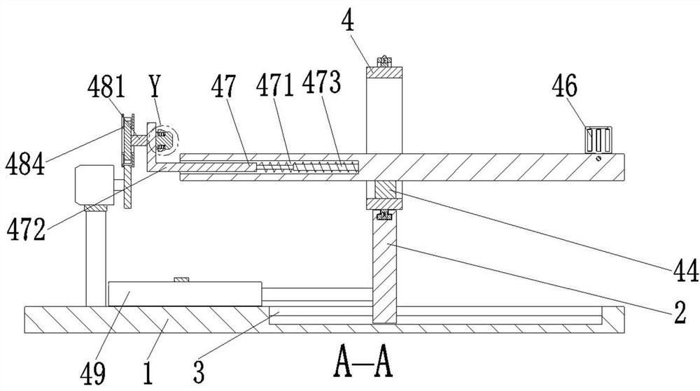
[0032] refer to figure 1 with image 3 , an automatic welding equipment for pipelines, comprising a base 1, a mounting rod 2, a chute 3 and a docking device 4, the mounting rods 2 are symmetrically arranged on the left and right sides of the upper end surface of the base 1, and the left side of the upper end of the base 1 is provided with The chute 3, the installation rod 2 on the left side is slidably arranged in the chute 3, the installation rod 2 on the right side is fixed on the base 1, and the upper end of the installation rod 2 is connected with the docking device 4.

[0033] refer to figure 1 , image 3 with Figure 4, the docking device 4 includes a limit ring 41, a positioning mechanism 42, a mounting ring 43, a connecting block 44, a p...


PUM


Abstract

The present invention relates to the technical field of pipeline processing, in particular to an automatic pipeline welding equipment and welding method, including a base, a mounting rod, a chute and a docking device. The left and right sides of the upper end surface of the base are symmetrically provided with mounting rods. There is a chute on the left side of the upper end, the installation rod on the left is slidingly set in the chute, the installation rod on the right is fixed on the base, and the upper end of the installation rod is connected with a docking device; For square steel pipes, the butt tightness cannot be guaranteed, the welding effect is not good, and it is necessary to continuously move the pipes to make the butt joints, which increases the burden on the staff; the present invention designs a limited clamping method for square steel pipes. And the machine for welding after butt joint ensures that the welding position is always in a tight state during welding, and there is no need to manually move the joint position, which reduces the burden on the staff.

Description

technical field [0001] The invention relates to the technical field of pipeline processing, in particular to an automatic pipeline welding equipment and welding method. Background technique [0002] Pipes are divided into plastic pipes and metal pipes according to their materials. Among them, steel pipes are steel products with a hollow section whose length is much longer than the diameter or circumference. Steel pipes are economical steel products that can be used to transport fluids and powdery solids. In the manufacture of mechanical parts, etc., steel pipes can be classified into round steel pipes, square steel pipes, rectangular steel pipes and special-shaped steel pipes according to the cross-sectional shape. Among them, the square steel pipes need to be welded to meet the length of use. [0003] At present, when welding square steel pipes, there are usually the following defects: 1. The traditional butt welding machine needs to clamp and butt two square steel pipes fi...

Claims


Application Information

Patent Timeline
Patent Type & Authority Patents(China)
IPC IPC(8): B23K37/00B23K37/04B23K101/06
CPCB23K37/00B23K37/0443B23K2101/06
Inventor 李娜罗社新罗寅东
Owner 江苏德邦流体控制有限公司
Why Eureka
Try Eureka