
PIN needle dissembling device and PIN dissembling head

A technology of dismantling device and actuating device, which is applied in the direction of assembling printed circuits with electrical components, can solve the problems of fast dismantling of PIN needles, easy injury to equipment operators, broken PIN needles, etc., so as to improve production efficiency and reduce Production cost, effect of reducing possibility

Inactive Publication Date: 2010-08-18
NANTONG HUALONG MICROELECTRONICS
View PDF3 Cites 8 Cited by
  • Summary
  • Abstract
  • Description
  • Claims
  • Application Information

AI Technical Summary

Problems solved by technology

That is, the distance between the lower surface of the copper sleeve and the upper surface of the tool plate is the protective part of the removal PIN needle without the copper sleeve. When removing the PIN, the removal of the PIN needle is prone to uneven force at the bottom and the removal of the PIN needle protruding from the bottom of the copper sleeve. There is no copper ferrule, which causes the PIN needle to break from the non-sheathed part. The PIN needle with a sharp fracture and disconnection is very fast, and it is easy to hurt the equipment operator and colleagues in the surrounding positions, posing a great safety hazard.

Method used


Image

  • PIN needle dissembling device and PIN dissembling head
  • PIN needle dissembling device and PIN dissembling head
  • PIN needle dissembling device and PIN dissembling head

Examples


Embodiment Construction

[0026] In order to describe the technical content, structural features, achieved goals and effects of the present invention in detail, the following will be described in detail in conjunction with the embodiments and accompanying drawings.

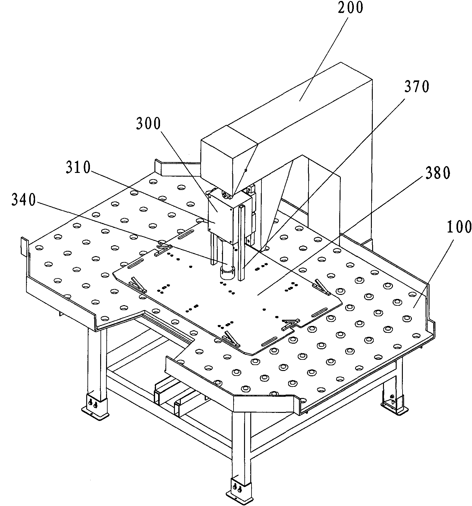
[0027] see figure 1 and figure 2 , the PIN pin removal device embodiment of the present invention comprises:

[0028] A workbench 100 carrying boards that need to be removed from the PIN;

[0029] a cantilever 200 located above the workbench 100;

[0030] The PIN needle fixed under the cantilever 200 removes the PIN head, and the PIN head includes:

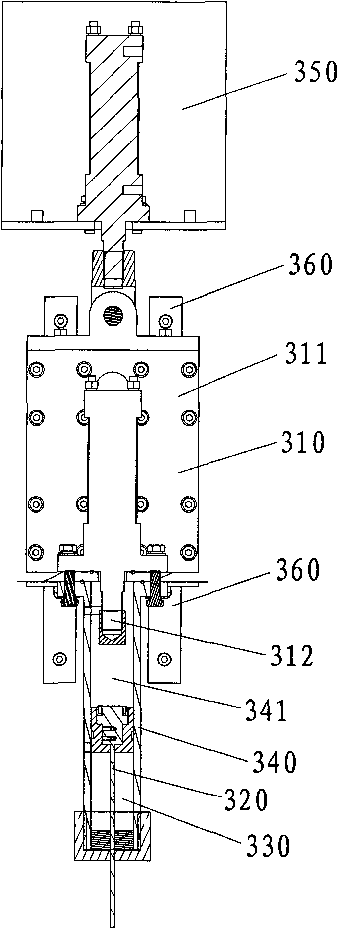
[0031] At least one actuating device 300, including a base 311 and an actuating rod 312 protruding from the base 311;

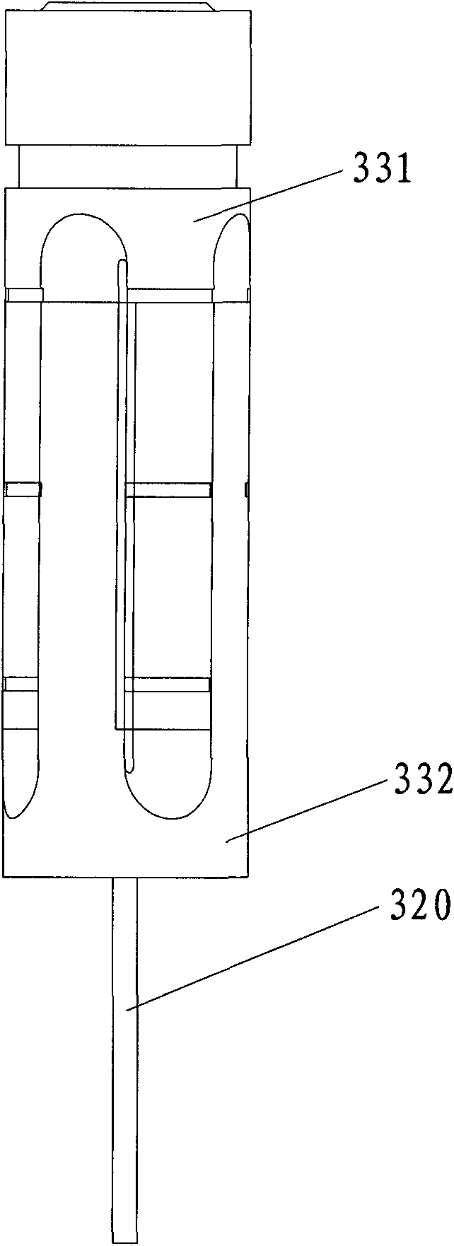
[0032]Corresponding to the end of the actuating rod 312 and coaxial with the actuating rod 312 is a PIN removal needle 320 and a protective sleeve 330 . refer to image 3 , Figure 4 and Figure 5 , the protective cover 330 includes a first sleeve body 331 and a seco...


PUM


Abstract

The invention discloses a PIN needle dissembling device and a PIN dissembling head thereof. The PIN dissembling head comprises at least one actuating device, a PIN dissembling needle and a protective sleeve thereof and a jacket. The at least one actuating device comprises a pedestal and an actuating rod extending out of the pedestal. The PIN disassembling needle and the protective sleeve are arranged corresponding to the tail end of the actuating rod and are coaxial with the actuating rod. The protective sleeve comprises a first sleeve body and a second sleeve which are embedded with each other, are opposite to each other and slide along opposite directions ; the axle centers of two sleeve bodies are accommodating passages of the PIN needles; the first sleeve body is adjacent to the actuating rod and fixed with one end of the PIN dissembling rod; the PIN dissembling needle is matched with the second sleeve body in a sliding manner and extends out of the tail end of the second sleeve body when two sleeve bodies slide relatively to the nearest distance. The jacket is used for accommodating the actuating rod, the PIN disassembling needle and the openings at two ends of the protective sleeve, one end of the jacket is fixed with the pedestal; the jacket is internally provided with an axial work passage for the sliding of the protective sleeve; and the work passage is longer than the nearest distance when two sleeve bodies slide relative to the nearest distance. The invention effectively protects the PIN dissembling needle, prevents the occurrence of accidents and improves the efficiency.

Description

technical field [0001] The invention relates to the technical field of printed circuit board (PCB) production equipment, in particular to a PIN needle removal device and a PIN removal head thereof. Background technique [0002] After the PIN board in PCB production is subjected to high-temperature lamination, the PIN pins on the PIN board need to be disassembled. [0003] In the prior art, the dismantling PIN head of the PIN needle includes an upper fixing seat A, a lower fixing seat B, an upper oil cylinder, a lower oil cylinder, a jacket fixed on the bottom of the lower oil cylinder and arranged vertically, a copper sleeve sliding up and down inside the jacket, and a clamping In the copper sleeve and the top end is fixed on the PIN pin at the end of the telescopic rod of the lower oil cylinder. The upper oil cylinder and the lower oil cylinder are respectively fixed on the upper fixed seat A and the lower fixed seat B. The fixed seat A is a hard fixed that cannot move, a...

Claims


Application Information

Patent Timeline
IPC IPC(8): H05K3/30
Inventor 彭维韩力陈念明肖海清
Owner NANTONG HUALONG MICROELECTRONICS
Learn More