
Light source system

A light source system and light source technology, applied in the field of light source systems, can solve the problems of increasing volume, poor picture effect, laser diode speckle, etc., and achieve the effect of reducing volume

Pending Publication Date: 2021-11-23
APPOTRONICS CORP LTD
View PDF5 Cites 1 Cited by
  • Summary
  • Abstract
  • Description
  • Claims
  • Application Information

AI Technical Summary

Benefits of technology

This patented technology allows for multiple different colored lights from an LED (light emitting device) chip that are mixed together into white light without causing any color distortion during transmission. It also reduces the size of the entire light source by providing more space between neighbored lamps instead of just adding extra components like filters.

Problems solved by technology

The technical problem addressed by this patented solution relates to improving image quality when displaying images through laser displays without causing annoying noises caused by specks or ghost effects that can occur during use. Current methods involve adding an anti-speckling layer before the optical components, such as prismatic layers, to reduce these issues. This approach adds extra costs while also reducing the overall efficiency of the system.

Method used


Image

  • Light source system
  • Light source system
  • Light source system

Examples


Embodiment Construction

[0012] The following will clearly and completely describe the technical solutions in the embodiments of the application with reference to the drawings in the embodiments of the application. Apparently, the described embodiments are only some of the embodiments of the application, not all of them. Based on the embodiments in this application, all other embodiments obtained by persons of ordinary skill in the art without making creative efforts belong to the scope of protection of this application.

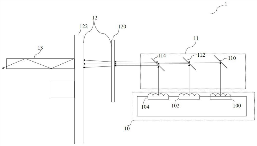
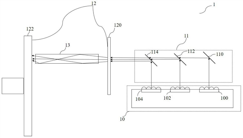
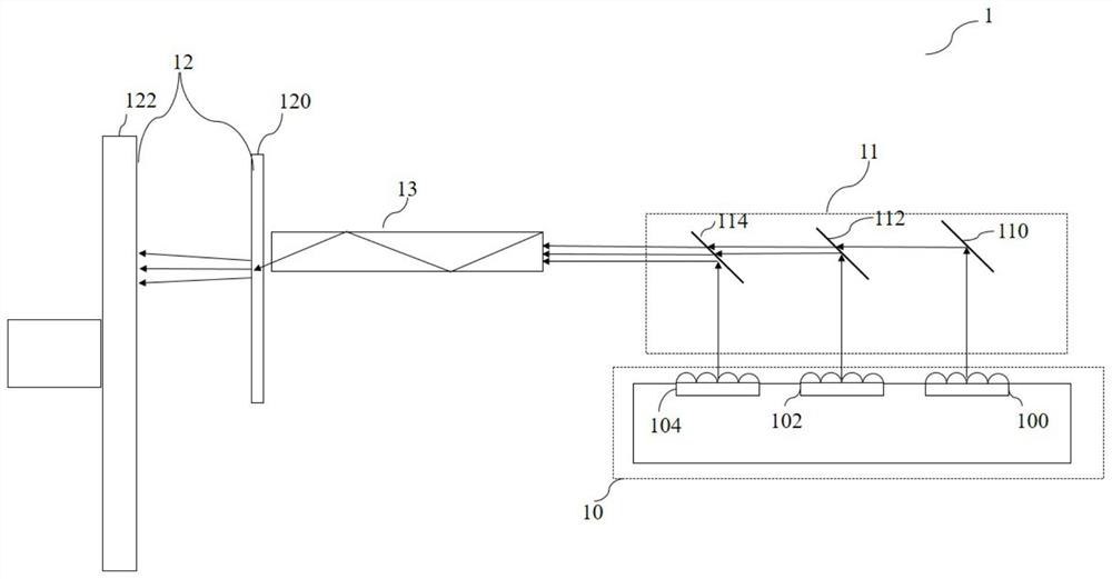
[0013] According to some embodiments of the present application, such as Figure 1-3 As shown, a light source system 1 is disclosed, including a light source 10, a light splitting and combining component 11, a scattering component 12, and a uniform light element 13, wherein,

[0014] The light source 1 includes a plurality of laser diodes or laser diode arrays for generating laser light, the laser light includes at least a first wavelength light and a second wavelength light, and th...


PUM

PropertyMeasurementUnit
Thicknessaaaaaaaaaa
Thicknessaaaaaaaaaa

Abstract

A light source system comprises a light source, a light splitting and combining assembly, a scattering assembly and a dodging element; the light source comprises a plurality of laser diodes or laser diode arrays and is used for generating laser, the laser comprises at least first wavelength light and second wavelength light, and the first wavelength light and the second wavelength light are different in color or wavelength; the light splitting and combining assembly is used for combining the laser to form a combined light beam; the scattering assembly is used for scattering and dodging the combined light beam, the scattering assembly comprises a first scattering element and a second scattering element, and the first scattering element and the second scattering element are independently arranged; the dodging element is located between the scattering assembly and the light splitting and combining assembly or located behind the scattering assembly or located between the first scattering element and the second scattering element and used for dodging of light beams entering the dodging element. According to the light source system, the multicolor laser is scattered through the two scattering elements which are independently arranged, the scattering effect is achieved, the size of the light source system is reduced, and light loss is reduced.

Description


Claims


Application Information

Patent Timeline
Owner APPOTRONICS CORP LTD
Learn More