
In-groove roller bed full-immersion type salt bath heat treatment device

Pending Publication Date: 2021-11-23
东营恒基石油科技有限公司
View PDF2 Cites 0 Cited by
  • Summary
  • Abstract
  • Description
  • Claims
  • Application Information

AI Technical Summary

Problems solved by technology

[0006] Compared with the traditional horizontal roller table, this "skewed roll" structure has disadvantages such as limited product specifications, easy detachment of wire rods, and difficulties in post-rolling treatment. Salt bath treatment of parts
[0007] In addition, in the manufacturing process of mechanical parts represented by large-size bearings, salt bath heat treatment is widely used. This type of equipment uses elevators to enter and exit the salt bath tank instead of continuous passing. The work of the heating furnace is continuous, which causes energy consumption. waste, and cannot adapt to mass production

Method used


Image

  • In-groove roller bed full-immersion type salt bath heat treatment device
  • In-groove roller bed full-immersion type salt bath heat treatment device
  • In-groove roller bed full-immersion type salt bath heat treatment device

Examples


Embodiment 1

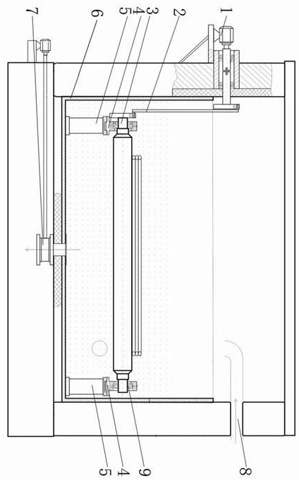
[0044] see Figure 1 to Figure 4 , a fully submerged salt bath heat treatment device with a roller table in a tank, comprising a salt bath tank 6, a motor 1 and a support 5.

[0045] Wherein, the bottom of the salt bath tank 6 is provided with a base, the two sides of the salt bath tank 6 are provided with insulation walls, and the top of the insulation wall is provided with an insulation cover.

[0046] A plurality of conveying rollers 3 are arranged in the salt bath tank 6 , and a continuous conveying roller table is formed by the plurality of conveying rollers 3 .

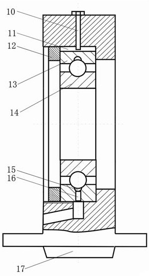
[0047] Both ends of each conveying roller 3 are installed in the salt bath tank 6 through the support 5 and below the molten salt liquid level. The top of the support 5 is detachably connected to the bearing seat 4, and the bearing seat 4 is equipped with a bearing 9. The bearing 9 The inner ring 14 is connected to the end of the conveying roller 3 .

[0048] The motor 1 is installed outside the salt bath tank...

Embodiment 2

[0054] The main reasons for bearing damage caused by molten salt are: first, the sediment or scale in the molten salt accumulates in the raceway of the outer ring of the bearing, causing wear to the bearing 9; second, when the salt bath stops working, it is necessary to put the salt bath 6 The molten salt in the inner ring is emptied, and the molten salt accumulated in the raceway of the outer ring cannot be discharged. Crystallized salt is produced after the temperature drops, and the bearing 9 is damaged due to ball rolling.

[0055] In order to solve the above problems, this embodiment is further optimized on the basis of embodiment 1, specifically:

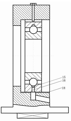
[0056] An annular sewage discharge groove 15 is processed on the raceway of the outer ring 13 of the bearing 9, and the bearing housing 4 is correspondingly provided with an interconnected sewage discharge channel 16, and one end of the sewage discharge flow channel 16 communicates with the sewage discharge groove 15 of the bea...

Embodiment 3

[0063] This embodiment is further optimized on the basis of the foregoing embodiments, specifically:

[0064] A bearing cap 12 for fixing the bearing 9 is installed on the bearing block 4 at the power end of the conveying roller 3 .

[0065] The bearing 9 at the other end is axially slidably installed in the bearing seat 4, and the bearing seat 4 is provided with a groove 18 vertically intersecting and communicating with the sewage flow channel 16. The function of the groove 18 is to prevent the axial displacement of the bearing 9. , keep the sewage flow channel 16 unimpeded.

[0066] Through the design that the bearing 9 on one side of the conveying roller 3 is fixedly installed, and the bearing 9 on the other side is axially slidably installed, there is room for the elongation of the conveying roller 3 due to thermal deformation, and the performance of the conveying roller 3 in high-temperature molten salt is improved. stability.

[0067] In addition, a positioning groove ...


PUM


Abstract

The invention relates to an in-groove roller bed full-immersion type salt bath heat treatment device. The in-groove roller bed full-immersion type salt bath heat treatment device comprises a salt bath groove, supports and a motor, a plurality of conveying rollers are arranged in the salt bath groove, and a continuous conveying roller way is formed through the conveying rollers; the two ends of each conveying roller are installed in the salt bath groove through the supports, the motor is installed outside the salt bath groove, and a transmission mechanism is arranged between the motor and the conveying rollers. According to the in-groove roller bed full-immersion type salt bath heat treatment device, a support and a conveying roller can be wholly immersed below the molten salt liquid level of the salt bath groove, so that all parts are heated uniformly, thermal deformation is kept consistent, and the in-groove roller bed full-immersion type salt bath heat treatment device can normally operate in high-temperature molten salt.

Description

technical field [0001] The invention relates to the technical field of heat treatment equipment, in particular to a fully submerged salt bath heat treatment device with roller tables in a tank. Background technique [0002] Salt bath heat treatment has a fast cooling rate at high temperature and a slow cooling rate at low temperature. This nearly ideal cooling characteristic and the adjustable cooling capacity play an important role in improving the high-strength comprehensive properties of materials. [0003] The transmission roller installed on the traditional salt bath needs to pass through the two side walls of the salt bath, and the two ends of the transmission roller and the salt bath need to be rotated and installed, and the temperature of the salt bath in the salt bath is generally 300~600°C, so the high temperature The sealing performance is not guaranteed, and only the middle part of the conveying roller is immersed in the molten salt, and the overall thermal defor...

Claims


Application Information

Patent Timeline
Patent Type & Authority Applications(China)
IPC IPC(8): C21D1/64C21D1/607C21D11/00
CPCC21D1/64C21D1/607C21D11/00
Inventor 卢明忠吕胜全
Owner 东营恒基石油科技有限公司
Learn More