
Laser etching machine for touch screen processing

Inactive Publication Date: 2021-11-23
深圳市睿尚创力科技有限公司
View PDF1 Cites 0 Cited by
  • Summary
  • Abstract
  • Description
  • Claims
  • Application Information

AI Technical Summary

Problems solved by technology

[0005] In order to improve the problem that the laser etching machine in the related art needs manual frequent pick and place of the touch screen, the application provides a laser etching machine for touch screen processing

Method used


Image

  • Laser etching machine for touch screen processing
  • Laser etching machine for touch screen processing
  • Laser etching machine for touch screen processing

Examples


Embodiment Construction

[0060] The following is attached Figure 1-9 The application is described in further detail.

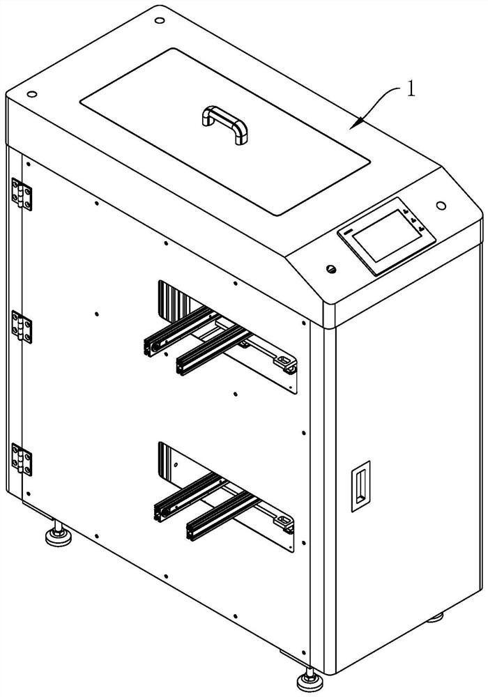
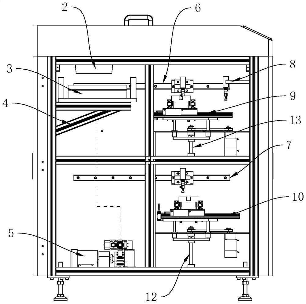
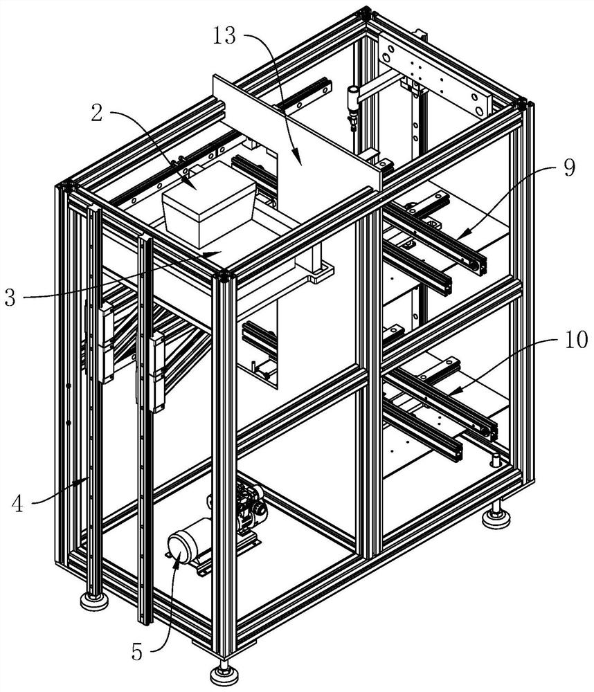
[0061] The embodiment of the present application discloses a laser etching machine for touch screen processing. refer to figure 1 and figure 2 , the laser etching machine includes a frame 1, a high-frequency pulse laser 2, a four-axis high-precision workbench 3, a first elevator 4, an exhaust device 5, a first retrieving device 6, a second retrieving device 7, a third retrieving device material device 8, the first translation assembly 9, the second translation assembly 10 and the lifting assembly; wherein, the inside of the frame 1 passes through a vertical isolation plate 13 ( image 3 (shown in the middle) is divided into an etching area and a transfer area arranged along the length direction of the rack 1, and the transfer area is divided into a feeding area and a discharging area along the height direction of the rack 1.

[0062] refer to figure 2 and image 3 , the high-...


PUM


Abstract

The invention relates to a laser etching machine for touch screen processing, and relates to the technical field of touch screen processing. The laser etching machine comprises a rack, a high-frequency pulse laser, a four-axis high-precision workbench, a first elevator, an air draft device, a first material taking device, a second material taking device, a third material taking device, a first translation assembly, a second translation assembly and a lifting assembly, wherein the interior of the rack is divided into an etching area and a transfer area which are arranged in the length direction of the rack through a vertically-arranged partition plate, and the interior of the transfer area is divided into a feeding area and a discharging area in the height direction of the rack. The laser etching machine has the effect that a touch screen does not need to be frequently taken and placed manually.

Description

technical field [0001] The present application relates to the technical field of touch screen processing, in particular to a laser etching machine for touch screen processing. Background technique [0002] The capacitive touch screen is a four-layer composite glass screen. The inner surface and the interlayer of the glass screen are each coated with a layer of ITO. The outermost layer is a thin layer of silica glass protective layer. The ITO coating is used as the working surface. When a finger touches the metal layer, a coupling capacitance is formed between the user and the surface of the touch screen. For high-frequency currents, the capacitance is a direct conductor, so the finger draws a small current from the contact point, and the current is divided into Flow out from the electrodes on the four corners of the touch screen, and the current flowing through these four electrodes is proportional to the distance from the finger to the four corners. The controller obtains t...

Claims


Application Information

Patent Timeline
Patent Type & Authority Applications(China)
IPC IPC(8): B23K26/362B23K26/142B23K26/70
CPCB23K26/362B23K26/142B23K26/702
Inventor 李林养冯荣珊
Owner 深圳市睿尚创力科技有限公司
Learn More