
High-frequency triggered direct-current welding power source

A welding power source and high-frequency technology, applied in the field of high-frequency-triggered DC welding power sources, can solve problems such as affecting the stability of the DC arc welding power source, adversely affecting the heat dissipation of power components, affecting the load duration rate of the DC arc welding power source, etc. The effect of heat dissipation, compactness improvement, and energy recovery improvement

Inactive Publication Date: 2021-11-23
深圳比斯特自动化设备有限公司
View PDF1 Cites 2 Cited by
  • Summary
  • Abstract
  • Description
  • Claims
  • Application Information

AI Technical Summary

Problems solved by technology

[0003] The purpose of the present invention is: in order to solve whether the welding process is stable or not is determined by the frequency of the current, the higher the current frequency, the more stable the output, the higher the welding quality, the higher the output power of the DC arc welding power source triggered by high frequency, the generated The higher the heat, the tighter the distribution of the built-in electronic components of the high-frequency triggered DC arc welding power supply is, which is not conducive to the heat dissipation of the power components, thus affecting the load duration of the high-frequency triggered DC arc welding power supply, and thus affecting the high-frequency arc welding power supply. Due to the stability of the triggered DC arc welding power supply, a high-frequency triggered DC welding power supply is proposed

Method used


Image

  • High-frequency triggered direct-current welding power source
  • High-frequency triggered direct-current welding power source
  • High-frequency triggered direct-current welding power source

Examples


Embodiment 1

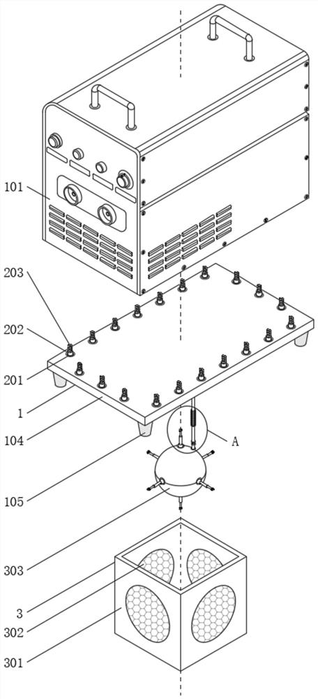
[0042] see Figure 1-8 , the present embodiment discloses a high-frequency triggering DC welding power supply, including an outer protective sound insulation assembly 1, a heat dissipation assembly 2 is arranged inside the outer protection sound insulation assembly 1, and the heat dissipation assembly 2 is used to generate an air vortex, and An air flow filter assembly 3 is also arranged at the position corresponding to the heat dissipation assembly 2 at the bottom of the outer protection sound insulation assembly 1, and an energy conversion assembly 4 is arranged inside the air flow filter assembly 3, and the energy conversion assembly 4 is used to realize the absorption of vibration energy. Digestion and conversion, the energy conversion component 4 communicates with the cooling component 2;

[0043] The heat dissipation assembly 2 includes a first spherical body 209, which is fixedly connected to the surface of the first adapter tube 202, and the surface of the first spheri...


PUM


Abstract

Herein The invention discloses a high-frequency triggered direct-current welding power source, and belongs to the technical field of welding equipment. The high-frequency triggered direct-current welding power source comprises an outer protection sound insulation component, wherein a heat dissipation component is arranged in the outer protection sound insulation component, and the heat dissipation component is used for generating air vortexes. According to the high-frequency triggered direct-current welding power source, through mutual cooperation of the designed structures such as the outer protection sound insulation component, the energy conversion component, the heat dissipation component and an air flow filtering component, air sprayed out of a spiral pipe can enter a direct-current arc welding power source case in a spiral shape, the radiation range of low-temperature air is enlarged, and in addition, heat in cracks of electronic components in the direct-current arc welding power source case can be quickly dissipated by means of attraction force generated by the spiral air flow. Therefore, the heat dissipation effect is further improved, energy recovery is conducted in the whole stroke of vibration, waste energy utilization is facilitated, and the shock resistance of the direct-current arc welding power source is further improved.

Description

technical field [0001] The invention belongs to the technical field of welding equipment, and in particular relates to a high-frequency triggering DC welding power supply. Background technique [0002] DC welding power supply is currently widely used in the field of welding. With the development trend of large-scale equipment, the demand for high-power welding power supply is also increasing. For example, the prior art discloses a digital multifunctional power supply based on plasma arc technology (patent No.: CN110026665A), the technical problem solved by this patent is that the performance of the welding power source determines the welding quality and efficiency, and it is the core equipment for realizing plasma arc welding cutting. The existing inverter type plasma welding power source still uses analog circuits for As a result, the pulsation characteristics of the plasma arc cannot be effectively adjusted, which greatly affects the welding quality and efficiency. It is e...

Claims


Application Information

Patent Timeline
Patent Type & Authority Applications(China)
IPC IPC(8): B23K9/10B23K9/32
CPCB23K9/10B23K9/32Y02P70/10
Inventor 钟晓荣
Owner 深圳比斯特自动化设备有限公司
Learn More