Mineral waste refractory material preparation process
A technology for refractory materials and waste, applied in the field of refractory materials, can solve problems such as affecting processing efficiency, component position deviation, equipment damage, etc., to improve the heating effect, avoid excessive heat dissipation, and improve the effect of thoroughness.
- Summary
- Abstract
- Description
- Claims
- Application Information
AI Technical Summary
Problems solved by technology
Method used
Image
Examples
Embodiment 1
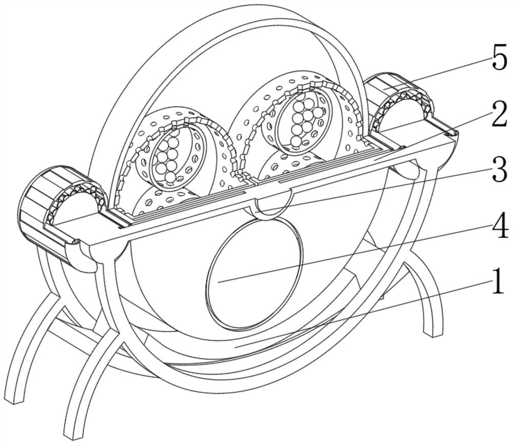
[0043] see Figure 1-6 , the present invention provides a technical solution: a mineral waste refractory preparation device, specifically comprising:
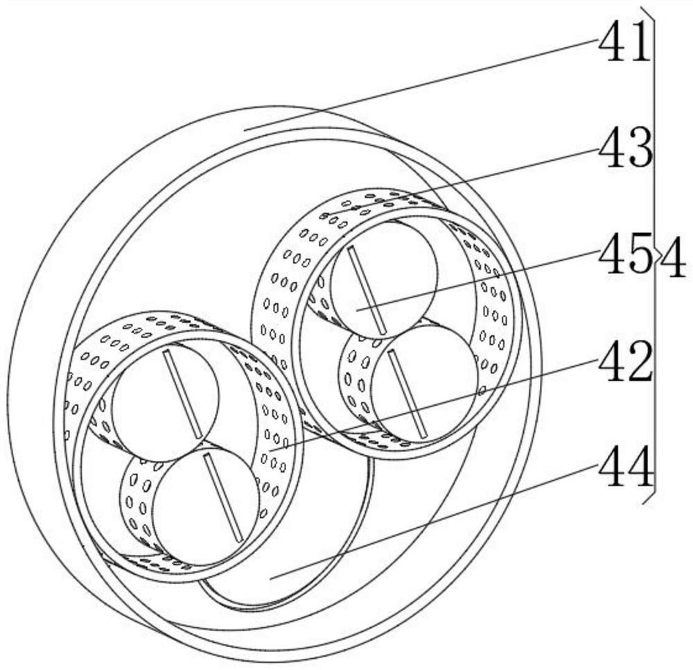
[0044]Install the placement seat 1, the installation placement seat 1 has a meniscus-shaped seat body, and an installation support plate 2 installed on the top of the meniscus-shaped seat body, and an installation sleeve 3 installed in the middle of the installation support plate 2, and installed on the Install the ball milling device 4 on the inner surface of the sleeve 3, and install the driving device 5 on the side where the mounting support plates 2 are close to each other and on both sides of the ball milling device 4. Through the setting of the mounting support plate 2 and the mounting sleeve 3, the ball milling device 4. Limit the position with the installation and placement base 1 to avoid mutual contact between components, and protect the surface wear of the ball mill 4 and the installation and placement base 1 to prev...
Embodiment 2
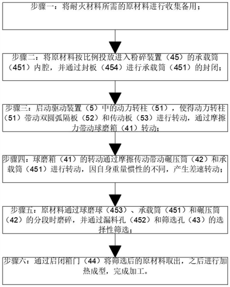
[0055] see Figure 1-6 On the basis of Embodiment 1, the present invention provides a technical solution: a preparation process of mineral waste refractory materials, comprising the following steps,
[0056] Step 1: Collect the raw materials required for refractory materials for later use;
[0057] Step 2: Put the raw materials into the inner cavity of the bearing cylinder 451 of the crushing device 45 in proportion, and seal the bearing cylinder 451 through the sealing plate 454:
[0058] Step 3: Start the power rotating column 51 in the driving device 5, so that the power rotating column 51 drives the double-arc partition 52 and the transmission plate 53 to rotate, and drives the ball mill box 41 to rotate through friction;
[0059] Step 4: The rotation of the ball mill box 41 drives the rolling cylinder 42 and the bearing cylinder 451 to rotate through friction transmission, and differential rotation occurs due to the difference in inertia of their own weight;
[0060] St...
PUM
 Abstract
Description
Claims
Application Information
 - Generate Ideas
- Intellectual Property
- Life Sciences
- Materials
- Tech Scout
- Unparalleled Data Quality
- Higher Quality Content
- 60% Fewer Hallucinations
Browse by: Latest US Patents, China's latest patents, Technical Efficacy Thesaurus, Application Domain, Technology Topic, Popular Technical Reports.
© 2025 PatSnap. All rights reserved.Legal|Privacy policy|Modern Slavery Act Transparency Statement|Sitemap|About US| Contact US: help@patsnap.com


