
Signal long-distance transmission phase stabilization system based on injection locking optoelectronic oscillator

A photoelectric oscillator and long-distance transmission technology, applied in the direction of electromagnetic wave transmission system, transmission system, electromagnetic receiver, etc., can solve the problems affecting the short-term stability of the system, the fiber frequency drift cannot be compensated in time, etc., to achieve high stability, phase Low noise, phase noise removal effect

Active Publication Date: 2021-11-19
BEIHANG UNIV
View PDF16 Cites 3 Cited by
  • Summary
  • Abstract
  • Description
  • Claims
  • Application Information

AI Technical Summary

Problems solved by technology

However, as the transmission distance (optical fiber length) increases, the frequency drift caused by the slow change of the optical fiber during transmission may be accumulated and cannot be compensated in time, and it is difficult to suppress the phase noise in the process of local oscillator signal generation, which is further superimposed on the remote On the phase noise spectrum of the terminal signal, the short-term stability of the system is affected during the mixing compensation

Method used


Image

  • Signal long-distance transmission phase stabilization system based on injection locking optoelectronic oscillator
  • Signal long-distance transmission phase stabilization system based on injection locking optoelectronic oscillator
  • Signal long-distance transmission phase stabilization system based on injection locking optoelectronic oscillator

Examples


example

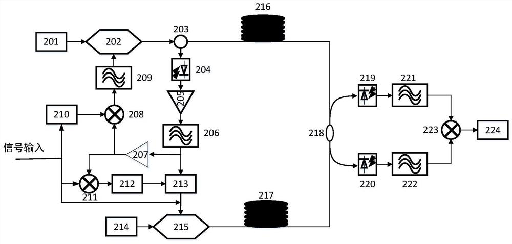
[0045] Such as image 3 An exemplary embodiment of the invention is shown. The method of the present invention is exemplarily applied to the most basic signal long-distance transmission phase-stabilization system structure based on injection-locked optoelectronic oscillators, and the free-running OEO, passive passive compensation scheme and passive compensation scheme based on injection-locked OEO are carried out Experimental comparison test. The specific implementation of the example is as follows: the main body of the OEO loop that generates the local oscillator signal consists of a continuous light source 314, an intensity modulator 315, long optical fibers 316, 317, a circulator 303, a photodetector 304, an electric amplifier 305 and a bandpass filter 306 Composition; the local reference microwave source is divided into three channels, one signal is multiplied by the frequency multiplier 310 and enters the mixer 308 to mix with the OEO loop oscillation signal to obtain a ...


PUM


Abstract

The invention relates to a signal long-distance transmission phase stabilization system based on an injection locking optoelectronic oscillator, and provides a local oscillator microwave signal long-distance stable-phase transmission implementation scheme with high frequency stability and low phase noise based on a passive compensation principle and an injection locking optoelectronic oscillator OEO microwave signal generation technology. On one hand, compared with a stable-phase transmission technology using an active compensation method, the scheme can be suitable for microwave signal transmission with a higher frequency band, a larger bandwidth and a better phase noise level. A traditional active compensation scheme has the disadvantage that an electric device limits the frequency band bandwidth and introduces electric heating noise. On the other hand, a common passive compensation scheme has the problems of relatively high phase noise level and the like, so that the short-term stability of a signal transmitted to a far end is limited. According to the invention, microwave signal stable-phase transmission can be applied more widely, and the defect of a traditional scheme on phase noise is made up.

Description

Technical field: [0001] The invention proposes a signal long-distance transmission phase stabilization system based on an injection-locked photoelectric oscillator, which relates to the research field of microwave photonics microwave signal phase stabilization transmission. Background technique: [0002] Today, high-stability local oscillator signal transmission over optical fiber is of great importance for various applications, such as remote clock synchronization and comparison, radio astronomy, distributed coherent aperture radar, etc. However, the transmission delay of optical fiber is affected by ambient temperature disturbance and pressure change, resulting in that the phase stability of the transmitted local oscillator microwave signal will be significantly degraded at the remote site. As the user's demand for frequency and stability of signal transmission continues to increase, the phase noise level and frequency of the traditional transmission structure can no longe...

Claims


Application Information

Patent Timeline
IPC IPC(8): H04B10/61
CPCH04B10/6163H04B10/6165
Inventor 谢正洋张开羽郑铮
Owner BEIHANG UNIV
Learn More