
Control method of air conditioning system and air conditioning system

A technology of an air-conditioning system and a control method, which is applied in the directions of air-conditioning system, heating and ventilation control system, heating and ventilation safety system, etc., can solve problems such as poor heating effect, and achieve reasonable distribution effect.

Inactive Publication Date: 2021-11-19
QINGDAO HAIER AIR CONDITIONING ELECTRONICS CO LTD +1
View PDF5 Cites 0 Cited by
  • Summary
  • Abstract
  • Description
  • Claims
  • Application Information

AI Technical Summary

Problems solved by technology

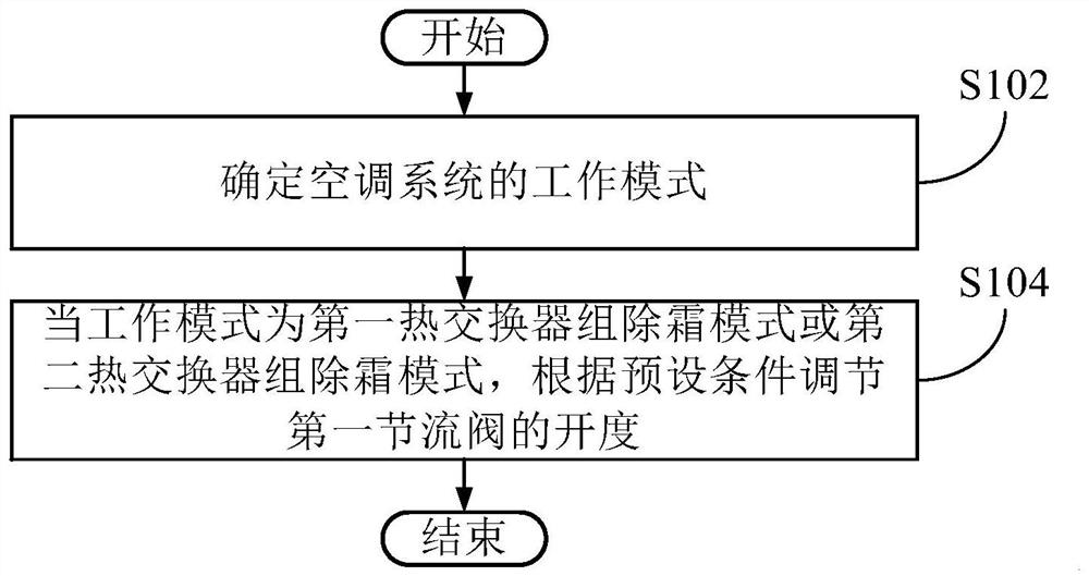
[0006] In order to solve the above-mentioned problems in the prior art, that is, in order to solve the problem of poor heating effect of the indoor unit when the outdoor heat exchanger defrosts in the existing air-conditioning units, the present invention provides a control method for the air-conditioning system. The air conditioning system includes a compressor, a first reversing device, a second reversing device, a first heat exchanger group, a second heat exchanger group, a gas pipe, a liquid pipe, an indoor unit and a first throttling device; the compressor The exhaust port of the compressor communicates with the first reversing device and the second reversing device at the same time, and the suction port of the compressor communicates with the first reversing device and the second reversing device at the same time; The two ends of the gas pipe communicate with the second reversing device and the indoor unit respectively; one end of the first heat exchanger group communicates with the first reversing device, and the other end communicates with the first reversing device through the liquid pipe. The indoor unit communicates; one end of the second heat exchanger group communicates with the first reversing device, and the other end communicates with the indoor unit through the liquid pipe; the first throttling device is located at the between the first reversing device and the exhaust port, and is used to adjust the flow of refrigerant flowing into the first reversing device; the first reversing device and the second reversing device are configured as follows: When the first heat exchanger group is defrosting, the gas pipe and the first heat exchanger group communicate with the exhaust port, and the second heat exchanger group communicates with the suction port; When the second heat exchanger group is defrosting, the air pipe and the second heat exchanger group are connected to the exhaust port, and the first heat exchanger group is connected to the suction port; The first heat exchanger group and the second heat exchanger group communicate with the exhaust port, and the gas pipe communicates with the suction port; when heating, the first heat exchanger group and the The second heat exchanger group communicates with the suction port, and the air pipe communicates with the exhaust port; the control method includes: determining the working mode of the air conditioning system, wherein the working mode includes cooling mode, Heating mode, defrosting mode of the first heat exchanger group, defrosting mode of the second heat exchanger group; when the working mode is the defrosting mode of the first heat exchanger group or the defrosting mode of the second heat exchanger group In defrosting mode, adjust the opening degree of the first throttling device according to preset conditions

Method used


Image

  • Control method of air conditioning system and air conditioning system
  • Control method of air conditioning system and air conditioning system
  • Control method of air conditioning system and air conditioning system

Examples


Embodiment 1

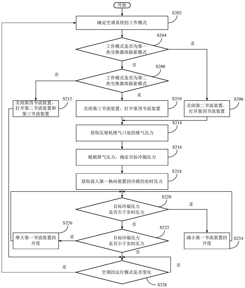
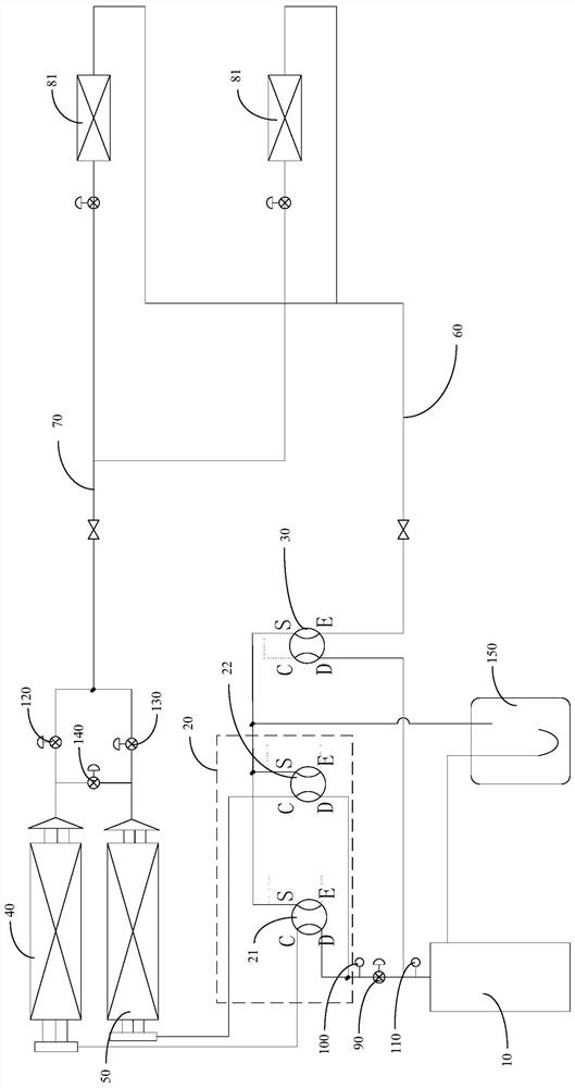
[0065] First refer to Figure 1 to Figure 3 , to describe the control method of the air conditioning system of the present invention. in, figure 1 It is a block flow diagram of the control method of the air conditioning system in the first embodiment of the present invention; figure 2 It is a block flow diagram of the control method of the air conditioning system in the first embodiment of the present invention; image 3 It is a structural schematic diagram of the air-conditioning system during cooling in the first embodiment of the present invention.

[0066] Such as Figure 1 to Figure 3 As shown, in order to solve the problem of poor heating effect of the indoor unit when the outdoor heat exchanger defrosts in the existing air-conditioning units, the present invention provides a control method for the air-conditioning system, wherein, refer to image 3, the air conditioning system includes a compressor 10, a first reversing device 20, a second reversing device 30, a fi...

Embodiment 2

[0106] Refer below Figure 3 to Figure 6 , describe the air conditioning system of the present invention. in, Figure 4 It is a structural schematic diagram of the air-conditioning system during heating in the first embodiment of the present invention; Figure 5 It is a structural schematic diagram of the first heat exchanger group 40 of the air-conditioning system during defrosting in the first embodiment of the present invention; Figure 6 It is a structural schematic diagram of the second heat exchanger group 50 of the air conditioning system during defrosting in the first embodiment of the present invention.

[0107] Such as Figure 3 to Figure 6 As shown, the present application also provides an air conditioning system, including: a compressor 10, a first reversing device 20, a second reversing device 30, a first heat exchanger group 40, a second heat exchanger group 50, an air pipe 60, liquid pipe 70, indoor unit (not shown in the figure), first throttling device 90 ...

Embodiment 3

[0138] Refer below Figure 7 to Figure 10 , to describe alternative implementations of the above-mentioned air conditioning system. in, Figure 7 It is a schematic diagram of the structure of the air-conditioning system during refrigeration in the second embodiment of the present invention; Figure 8 It is a schematic diagram of the structure of the air-conditioning system during heating in the second embodiment of the present invention; Figure 9 It is a structural schematic diagram of the first heat exchanger group 40 of the air-conditioning system during defrosting in the second embodiment of the present invention; Figure 10 It is a schematic structural diagram of the second heat exchanger group 50 of the air conditioning system during defrosting in the second embodiment of the present invention.

[0139] The difference between this embodiment and Embodiment 2 is that the first reversing device 20 includes a first electric control valve 23 , a second electric control va...


PUM


Abstract

The invention relates to the field of air conditioners, in particular to a control method of an air conditioning system and the air conditioning system. The problem that the heating effect of an indoor unit is poor when an outdoor heat exchanger of an air conditioning unit is defrosted is solved. An air suction port of a compressor of the air conditioning system communicates with a first reversing device and a second reversing device; two ends of an air pipe communicate with the second reversing device and the indoor unit; one end of a first heat exchanger group communicates with the first reversing device, and the other end of the first heat exchanger group communicates with the indoor unit through a liquid pipe; one end of a second heat exchanger group communicates with the first reversing device, and the other end of the second heat exchanger group communicates with the indoor unit through a liquid pipe; and a first throttling device adjusts the flow of a refrigerant flowing into the first reversing device. The control method comprises the steps that a working mode of the air conditioning system is determined; and when the working mode is the first heat exchanger group defrosting mode or the second heat exchanger group defrosting mode, the opening degree of the first throttling device is adjusted according to preset conditions. Therefore, when the first heat exchanger group or the second heat exchanger group is defrosted, the heating effect of the indoor unit can be guaranteed.

Description

technical field [0001] The invention relates to the technical field of air conditioning, in particular to a control method for an air conditioning system and an air conditioning system. Background technique [0002] When the existing air conditioner unit is in defrosting operation, it is generally switched to the cooling operation mode through the four-way valve reversing, the indoor heat exchanger is used as the evaporator, and the outdoor heat exchanger is used as the condenser, and the heat emitted by the condenser is condensed Melt the layer of frost. Therefore, during defrosting, since the indoor heat exchanger is an evaporator, the indoor ambient temperature will drop, which will bring users an uncomfortable experience. [0003] In order to solve the above technical problems, in the prior art, multiple outdoor heat exchangers are set up on the basis of ordinary multi-connector units, and a high-temperature pipe is drawn from the exhaust port of the compressor and conn...

Claims


Application Information

Patent Timeline
Patent Type & Authority Applications(China)
IPC IPC(8): F24F11/42F24F11/64F24F11/70F24F11/89F25B47/02F25B49/02F25B13/00F25B41/30F25B41/20F24F140/12
CPCF24F11/42F24F11/64F24F11/70F24F11/89F25B47/02F25B49/02F25B13/00F24F2140/12F25B41/20F25B41/30F24F5/00
Inventor 罗建文毛守博卢大海何建奇
Owner QINGDAO HAIER AIR CONDITIONING ELECTRONICS CO LTD
Learn More