Wetland environment sewage treatment device and method
A sewage treatment device and environmental technology, applied in biological treatment devices, biological water/sewage treatment, water/sewage multi-stage treatment, etc., can solve problems such as affecting the growth of emergent plants, fluctuating sewage volume and reducing sewage purification effect
- Summary
- Abstract
- Description
- Claims
- Application Information
AI Technical Summary
Problems solved by technology
Method used
Image
Examples
Embodiment 1
[0040] According to an embodiment of the present invention,
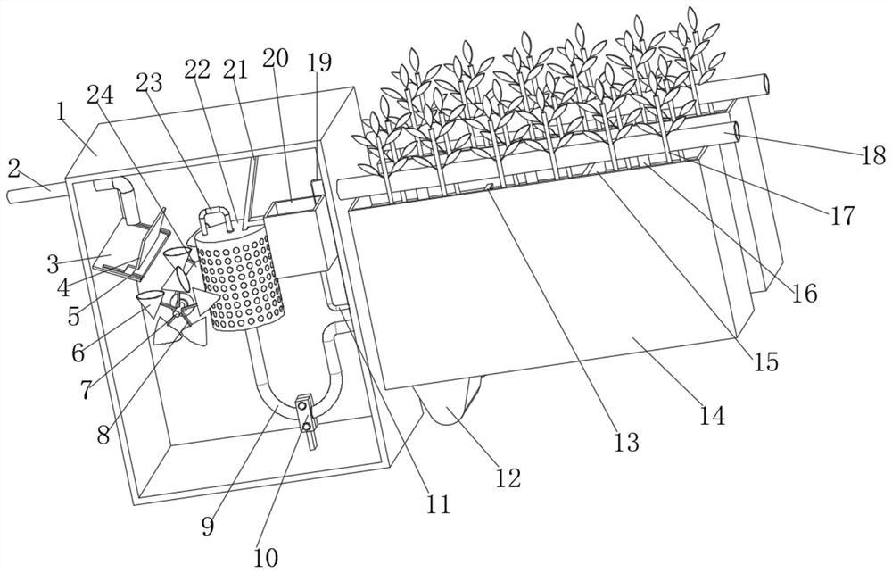
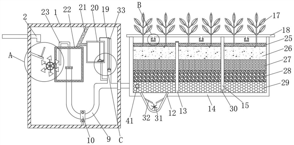
[0041] see Figure 1-8 , a wetland environmental sewage treatment device, comprising a box body 1 and a planting pond 14 arranged on one side of the box body 1, a liquid inlet pipe 2 is inserted into one side of the box body 1, and a pair of The diversion assembly for dispersing sewage, the diversion assembly is located below the liquid inlet pipe 2, the top inner wall of the box body 1 is fixedly connected with a fixed rod 21, one end of the fixed rod 21 is fixedly connected with a mesh cylinder 22, and the bottom of the mesh cylinder 22 is plugged with a Siphon tube 9, the top of siphon tube 9 is plugged with drainage tube 23, and drainage tube 23 is positioned at the inside of mesh cylinder 22, and one end of siphon tube 9 extends to the outside of box body 1, and the number of planting pools 14 is two groups, and two groups of planting pools 14 are respectively Located on both sides of the siphon tube 9, fixed ...
Embodiment 2
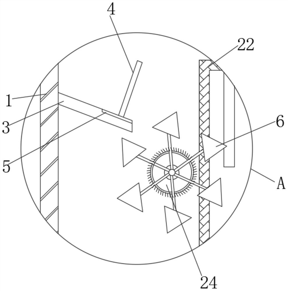
[0043] see Figure 1-3 , the diversion assembly includes a deflector 3 fixedly connected to the inner wall of one side of the box body 1, the top of the deflector 3 is fixedly connected with a baffle 4, the top of the deflector 3 is provided with a diversion groove 5, and the two sides of the box 1 The side inner walls are all rotatably connected with a rotating column 7, and one end of the rotating column 7 away from the casing 1 is fixedly connected with a brush roller 24, and the brush roller 24 is in contact with one side of the net tube 22, and the peripheral outer wall of the rotating column 7 is fixedly connected with a Connecting rod 8, one end of connecting rod 8 far away from rotating column 7 is fixedly connected with water collecting bucket 6, the cross section of water collecting bucket 6 is triangular, water collecting bucket 6 is located directly below diversion groove 5, and drainage tube 23 is far away from siphon tube 9 One end and the brush roller 24 are loc...
Embodiment 3
[0045] see figure 1 , 2 , 5, 6, the other end of the fixed rod 21 is fixedly connected with the water collection tank 20, the bottom of the water collection tank 20 is plugged with a catheter 11, and the end of the catheter 11 away from the water collection tank 20 is plugged with an overflow pipe 33. The liquid pipe 11 is connected with the overflow pipe 33, which can ensure that the work of the subsequent siphon pipe 9 can be carried out stably.
[0046] see figure 1 , 2 , 5, 6, the inside of the overflow pipe 33 is provided with a piston 38, the top of the piston 38 is fixedly connected with a traction rope 19, and the end of the traction rope 19 away from the piston 38 is bolted with a fixed ring 36, and the two ends of the fixed ring 36 are all fixedly connected There is a cover plate, the bottom of the cover plate is provided with a gasket 37, the bottom of the water collection tank 20 is fixedly connected with a connecting block, one side of the connecting block is c...
PUM
 Abstract
Description
Claims
Application Information
 - R&D
- Intellectual Property
- Life Sciences
- Materials
- Tech Scout
- Unparalleled Data Quality
- Higher Quality Content
- 60% Fewer Hallucinations
Browse by: Latest US Patents, China's latest patents, Technical Efficacy Thesaurus, Application Domain, Technology Topic, Popular Technical Reports.
© 2025 PatSnap. All rights reserved.Legal|Privacy policy|Modern Slavery Act Transparency Statement|Sitemap|About US| Contact US: help@patsnap.com


