
High power tunable CO2 laser

A carbon dioxide and laser technology, applied in the field of lasers, can solve problems such as inconvenience in laser design

Inactive Publication Date: 2004-01-28
INST OF ELECTRONICS CHINESE ACAD OF SCI
View PDF0 Cites 0 Cited by
  • Summary
  • Abstract
  • Description
  • Claims
  • Application Information

AI Technical Summary

Problems solved by technology

In high power lasers, it is also necessary to increase the output window for reflectively coupled beams, which also brings inconvenience to the laser design

Method used

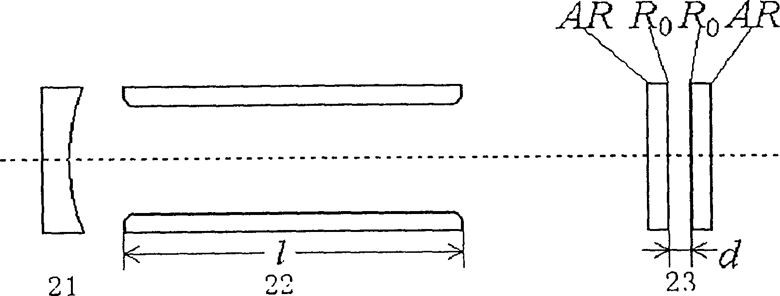

Image

  • High power tunable CO2 laser
  • High power tunable CO2 laser
  • High power tunable CO2 laser

Examples


Embodiment Construction

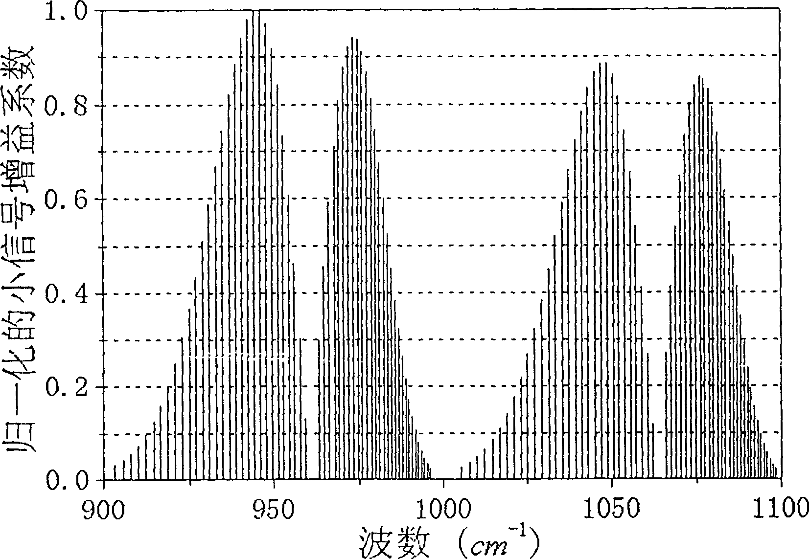
[0017] Please see first image 3 The normalized CO 2 Distribution of laser transition small-signal gain with frequency. CO 2 There can be about 100 laser transition lines in the wavelength range of 9 to 11 μm, which belong to four transition bands of 10P, 10R, 9P, and 9R (00°1-10°0 band and 00°1-02°0 band of P branch and R branch). It can be seen from the figure that the peak spectra of the four transition bands are 10P(20), 10R(18), 9P(20) and 9R(18), respectively. But a freely oscillating TEA CO without any dispersive element inside the cavity 2 In the laser, due to the result of gain competition, the laser output power is always concentrated on a spectral line with the highest gain. The 10P(20) transition line has the highest gain, so the freely oscillating TEA CO 2 The laser transition line output by the laser is 10P(20), and the laser frequency is 945cm -1 , with a wavelength of 10.6 μm.

[0018] In order to obtain the output of laser transition lines in other tra...


PUM


Abstract

The CO2 laser includes one spherial reflector, one CO2 laser discharging gain region, and one Fabry-Perot modulator and features that the Fabry-Perot modulator is as one terminal reflector of the laser resonant cavity and for laser power to be transmitted to couple output. With simple structure and stable performance, the CO2 laser may be applied in laser chemistry, atmosphere transmission, material machining and other fields.

Description

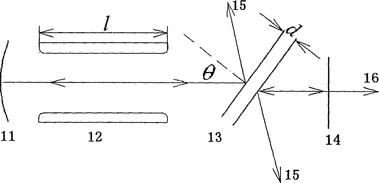
technical field [0001] The invention belongs to lasers, in particular to a high-power tunable carbon dioxide (CO 2 ) laser. Background technique [0002] Fabry-Perot interferometers are widely used in tunable lasers, especially tunable CO 2 in the laser. The commonly used technique is to insert a tilted Fabry-Perot interferometer in the laser cavity. figure 1 It is a tunable CO 2 Laser schematic. like figure 1 As shown, the laser resonator is composed of a spherical total reflection mirror 11 and a partially reflecting plane mirror 14 . A laser beam 16 is transmitted and coupled out from the plane mirror 14 . In addition to the laser gain region 12, a pair of Fabry-Perot interferometers 13 composed of parallel plane mirrors are inserted in the laser resonator. The distance between the plane mirrors is d, and the inner surfaces have the same reflectivity. anti-reflective film. The inclination θ of the rotating interferometer can realize the tuning of the laser. The ...

Claims


Application Information

Patent Timeline
IPC IPC(8): H01S3/08H01S3/106
Inventor 万重怡万朋谭荣清吴谨
Owner INST OF ELECTRONICS CHINESE ACAD OF SCI
Learn More