Ophthalmic lenses for reducing myopic progression and methods of making the same

An ophthalmic lens, lens technology, applied in the direction of glasses/protective glasses, glasses/goggles, applications, etc.

Pending Publication Date: 2021-11-16
サイトグラスヴィジョンインコーポレイテッド
View PDF6 Cites 0 Cited by
  • Summary
  • Abstract
  • Description
  • Claims
  • Application Information

AI Technical Summary

Problems solved by technology

However, in myopic individuals, the relative eye axial length for overall eye size continues to increase during development beyond the length that provides near-optimal focus on distant objects, causing myopia to become increasingly pronounced

Method used


Image

  • Ophthalmic lenses for reducing myopic progression and methods of making the same
  • Ophthalmic lenses for reducing myopic progression and methods of making the same
  • Ophthalmic lenses for reducing myopic progression and methods of making the same

Examples


Embodiment Construction

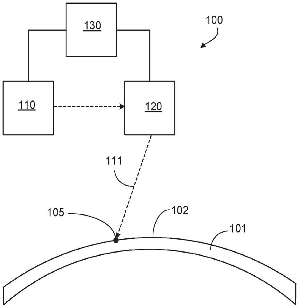
[0049] refer to figure 1 , a laser system 100 for forming optical elements 105 on a surface 102 of a conventional ophthalmic lens 101 includes a laser 110 and a beam directing assembly 120 each in communication with a controller 130 (eg, a computer controller). Laser 110 directs the laser beam towards a beam directing assembly that directs and focuses beam 111 towards optic 101 , which is positioned relative to assembly 120 by a stage (not shown). For example, beam directing assembly 120 may include actuated mirrors and one or more optics to vary the direction and focus of laser radiation. Controller 130 coordinates the operation of laser 110 and beam directing assembly 120 to expose surface 102 to pulses of laser radiation at discrete locations on the lens to form optical elements in a predetermined pattern on the lens surface.

[0050] In some implementations, the gantry also includes an actuator. The stage actuator may be a multi-axis actuator, for example, moving the mir...


PUM

PropertyMeasurementUnit
sizeaaaaaaaaaa
diameteraaaaaaaaaa
sizeaaaaaaaaaa

Abstract

A method includes providing an ophthalmic lens having a prescribed optical power, the ophthalmic lens having a surface having a base curvature corresponding to the prescribed optical power, and exposing a material at the surface to laser radiation sufficient to locally reshape the material to form a plurality of lenslets on the surface. The lenslets each have a corresponding optical power that differs from the prescribed optical power of the ophthalmic lens.

Description

[0001] Cross References to Related Applications [0002] This application claims priority to Provisional Application No. 62 / 812,639, filed March 1, 2019, the entire contents of which are incorporated herein by reference. Background technique [0003] The eye is an optical sensor in which light from an external source is focused through the lens onto the surface of the retina, an array of wavelength-dependent photoreceptors. The lens of the eye can accommodate by changing its shape so that external light rays are optimally or nearly optimally focused to produce a focal length on the surface of the retina that corresponds to the inverted image of the external image observed by the eye. The lens of the eye focuses optimally or nearly optimally on light emitted by or reflected from external objects within a certain distance from the eye, and less optimally or fails to focus on objects outside that distance range. [0004] In individuals with normal vision, the axial length of the...

Claims


Application Information

Patent Timeline
Patent Type & Authority Applications(China)
IPC IPC(8): G02C7/00G02C7/02G02C7/06A61F2/16
CPCG02C7/022G02C2202/24B29D11/00326B29D11/00009B29D11/00451B29D11/00865
Inventor 彼得·霍内斯小托马斯·W·沙尔伯格
Owner サイトグラスヴィジョンインコーポレイテッド
Why Eureka
Try Eureka