Cathode flow channel of proton exchange membrane fuel cell for improving water removal effect
A fuel cell cathode, proton exchange membrane technology, applied in fuel cells, battery electrodes, circuits, etc., to achieve the effects of easy processing, increased specific surface area, and reduced power loss
- Summary
- Abstract
- Description
- Claims
- Application Information
AI Technical Summary
Problems solved by technology
Method used
Image
Examples
Embodiment 1
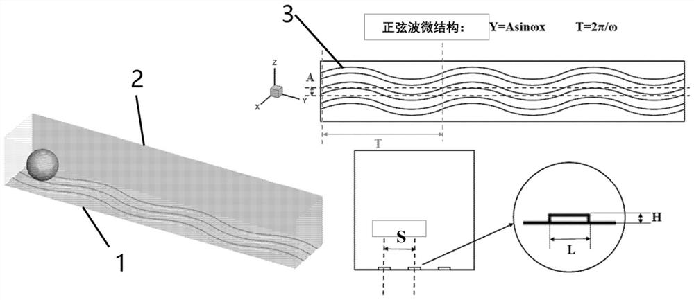
[0031] The optimized structure for water removal on the surface of the gas diffusion layer of a proton exchange membrane fuel cell. The flow channel of the fuel cell is divided into two regions, the cathode and the anode by the proton exchange membrane. The gas diffusion layer 1 is located below the cathode flow channel 2 . Such as figure 1 As shown, a gas diffusion layer structure of a proton exchange membrane fuel cell, the gas diffusion layer 1 is the base layer of the cathode channel, the material of the gas diffusion layer 1 is carbon fiber, and the surface of the gas diffusion layer 1 is provided with a micro-protrusion texture 3. It is used to strengthen the liquid water to leave the surface of the gas diffusion layer 1 and improve the "water flooding" phenomenon of the cathode of the proton exchange membrane fuel cell. The width and height of the cathode flow channel 2 are both 1.0 mm, and the length is 6.0 mm. The area of the micro-protrusion texture 3 accounts fo...
Embodiment 2
[0036] Such as Figure 5 As shown, the internal structure of the flow channel of a proton exchange membrane fuel cell, the width and height of the cathode flow channel 2 are both 1.0 mm, and the length is 6.0 mm, and the cathode flow channel 2 is selected from a section of the real flow channel for simulation. The hydrophilic tube 4 is embedded in the cathode flow channel 2 and fixed on the top of the cathode flow channel 2. The hydrophilic tube 4 is distributed parallel to the cross-sectional direction of the flow channel. Along the flow direction, the cross-section of the hydrophilic tube 2 is circular and the cross-sectional area remains unchanged. It is used to strengthen liquid water leaving the surface of gas diffusion 1, and improve the "water flooding" phenomenon of proton exchange membrane fuel cell cathode. The structure height of the hydrophilic tubes 4 is H=350-550 μm, the diameter of the hydrophilic tubes 4 is D=50-150 μm, the distance between the hydrophilic tube...
Embodiment 3
[0037] Embodiment 3: The hydrophilic tube 4 in the embodiment 2 is installed on the top of the cathode flow channel 2, and the micro-protrusion texture 3 in the embodiment 1 is installed at the bottom of the cathode flow channel 2, and the hydrophilic tube 4 and the micro-protrusion are used. Playing the joint role of texture 3 to realize the removal of liquid water on the surface of the gas diffusion layer and reduce the power loss.
PUM
| Property | Measurement | Unit |
|---|---|---|
| width | aaaaa | aaaaa |
| height | aaaaa | aaaaa |
| diameter | aaaaa | aaaaa |
Abstract
Description
Claims
Application Information
 - R&D Engineer
- R&D Manager
- IP Professional
- Industry Leading Data Capabilities
- Powerful AI technology
- Patent DNA Extraction
Browse by: Latest US Patents, China's latest patents, Technical Efficacy Thesaurus, Application Domain, Technology Topic, Popular Technical Reports.
© 2024 PatSnap. All rights reserved.Legal|Privacy policy|Modern Slavery Act Transparency Statement|Sitemap|About US| Contact US: help@patsnap.com


