
Clamping and fixing device for electrical detection equipment

A fixing device and electrical detection technology, applied in the direction of the measuring device shell, etc., can solve the problems of clamping and fixing restrictions, extrusion crushing, loosening, etc., and achieve the effect of clamping and fixing firmly

Inactive Publication Date: 2021-11-16
陈小青
View PDF0 Cites 2 Cited by
  • Summary
  • Abstract
  • Description
  • Claims
  • Application Information

AI Technical Summary

Problems solved by technology

[0004] The object of the present invention is to provide a clamping and fixing device for electrical testing equipment to solve the problem that the traditional electrical component clamping and fixing equipment proposed in the background technology mentioned above uses clips, and the clamping of the clips will be affected by electrical components. Due to the limitation of the shape and size of the component, there will be looseness in the clamping with irregular shape, which will bring some troubles to the later detection, so that the clamping and fixing are subject to certain restrictions, which is not conducive to the current use of electrical testing. However, it still needs manual operation and fastening during clamping, which makes it time-consuming and labor-intensive, and the electrical components will be squeezed and broken due to excessive artificial force.

Method used


Image

  • Clamping and fixing device for electrical detection equipment
  • Clamping and fixing device for electrical detection equipment
  • Clamping and fixing device for electrical detection equipment

Examples


Embodiment Construction

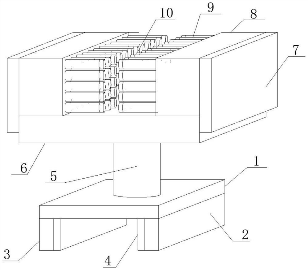
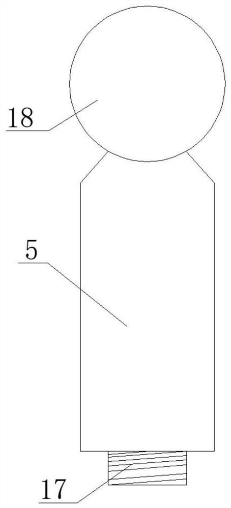
[0028] see Figure 1-2 , in an embodiment of the present invention, a clamping and fixing device for electrical testing equipment includes a bottom support plate 1, a fixed side plate 2 is welded to the bottom surface of the bottom support plate 1, a movable pressure plate 3 is connected to the bottom surface of the bottom support plate 1, and the fixed side plate The side between the plate 2 and the movable pressure plate 3 is fixedly bonded with a rubber backing plate 4, the top surface of the fixed side plate 2 is vertically fixed on the bottom surface of the bottom support plate 1 close to one side, and the top surface of the movable pressure plate 3 is connected The bottom surface of the bottom support plate 1 is far away from the side of the fixed side plate 2, and the movable platen 3 and the fixed side plate 2 are arranged parallel to each other. The rubber backing plate 4 is made of soft rubber material. The bottom support plate 1 An extension rod 5 is arranged vertic...


PUM


Abstract

The invention discloses a clamping and fixing device for electrical detection equipment and relates to the field of electrical detection. The clamping and fixing device for the electrical detection equipment comprises a bottom supporting plate, a fixed side plate is welded to the bottom surface of the bottom supporting plate, a movable pressing plate is connected to the bottom surface of the bottom supporting plate, a rubber cushion plate is fixedly bonded to a side edge between the fixed side plate and the movable pressing plate, an extension rod is vertically and upwards arranged on the top face of the bottom supporting plate, a fixed top plate is horizontally arranged at the top end of the extension rod, extrusion side plates are symmetrically arranged on the two side edges of the fixed top plate, fixed box bodies are fixedly bonded to side edges between the extrusion side plates, movable ejector rods are horizontally inserted into the side edges between the fixed box bodies, and rubber blocks are fixedly clamped at the ends, far away from the fixed box bodies, of the movable ejector rods. The device is simple in design structure; an electric induction clamping structure is adopted, so that operation is simpler, more convenient and quicker; and meanwhile, a wrapping type clamping mode is adopted, so that the device is not influenced by specifications and dimensions, and clamping is more stable and firmer.

Description

technical field [0001] The invention relates to the technical field of electric detection, in particular to a clamping and fixing device for electric detection equipment. Background technique [0002] Electrification has always been a symbol of the progress and development of human society. With the strong development momentum of China's economy. Various electrical devices are increasingly entering various fields of the national economy and people's lives. Electronic components are basic elements in electronic circuits, usually individually packaged, and have two or more leads or metal contacts. Electronic components must be connected to each other to form an electronic circuit with specific functions, such as amplifiers, radio receivers, oscillators, etc. One of the common ways to connect electronic components is to solder them to a printed circuit board. Electronic components may be individual packages (resistors, capacitors, inductors, transistors, diodes, etc.), or gro...

Claims


Application Information

Patent Timeline
Patent Type & Authority Applications(China)
IPC IPC(8): G01R1/04
Inventor 陈小青
Owner 陈小青
Learn More