
Fender compression performance detection device

A detection device and fender technology, which are applied in the field of fender compression performance detection devices, can solve the problems such as the location limitation of the fender compression detection, the inability to meet the compressibility detection of the fender circumference, and the inability of the relative position of the fender to be fixed. , to achieve the effect of firm clamping, reasonable structure and increased contact friction

Active Publication Date: 2021-11-16
江苏弘业检测技术有限公司
View PDF6 Cites 0 Cited by
  • Summary
  • Abstract
  • Description
  • Claims
  • Application Information

AI Technical Summary

Problems solved by technology

[0004] However, the above-mentioned device has the following disadvantages. The relative position of the fender is determined by Velcro, but the relative position of the larger fender cannot be fixed well, and when the compression detection component is used to press, the fender will be greatly affected. The pressure causes the position of the fender to move, making the detection result data inaccurate, and the location of the fender compression detection is limited, which cannot meet the peripheral compressibility detection of the fender. Therefore, this application provides a fender Onboard compression performance testing device to meet the demand

Method used


Image

  • Fender compression performance detection device
  • Fender compression performance detection device
  • Fender compression performance detection device

Examples


Embodiment

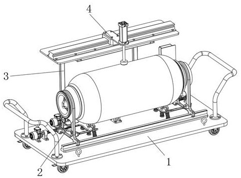
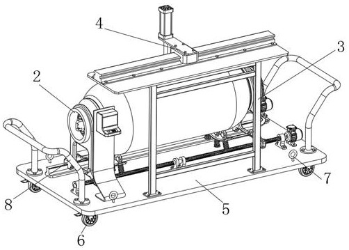
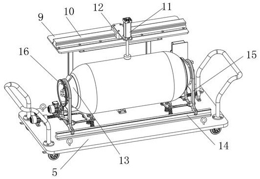
[0030] Example: Reference Figure 1-8 A fender compression performance testing device shown includes a mobile platform assembly 1, a fender limit clamping unit 2 and a frame 3 are installed on the top of the mobile platform assembly 1, and a movable fender is installed on the frame 3 The compression detection component 4, the fender compression detection component 4 is used to detect the compression performance of the fender;

[0031] The fender limit clamping unit 2 includes a connected moving assembly, a rotating clamping assembly and a support assembly 25, the moving assembly is used to move the rotating clamping assembly to clamp and limit the fender, and the rotating clamping assembly is used to clamp the fender The fender is rotated, and the support assembly 25 is used to support the fender;

[0032]It also includes a controller, the fender limit clamping unit 2 and the fender compression detection component 4 are connected to the controller signal;

[0033] Support as...


PUM


Abstract

The invention discloses a fender compression performance detection device, and relates to the technical field of fender performance detection. The fender compression performance detection device comprises a mobile platform assembly, a fender limiting and clamping unit and a rack are installed at the top of the mobile platform assembly, and a movable fender compression detection assembly is installed on the rack; the fender compression detection assembly is used for detecting the compression performance of the fender; the fender limiting and clamping unit comprises a moving assembly, a rotary clamping assembly and a supporting assembly which are connected, and the moving assembly is used for moving the rotary clamping assembly to clamp and limit the fender. The fender compression performance detection device is reasonable in structure, fenders with different lengths and sizes can be clamped and limited, clamping is firm, the practicability is improved, the fenders clamped between a pair of limiting and clamping shells can rotate, next-step compression performance detection can be conveniently carried out on the peripheries of the fenders, and compression performance detection on different positions in the length direction of the fender is achieved, and the detection range is widened.

Description

technical field [0001] The invention relates to the technical field of fender performance detection, in particular to a fender compression performance detection device. Background technique [0002] The fender, also known as the ship's guard, is an elastic buffer device used on the edge of the dock or ship. It is made of wood or rubber. It is mainly used to slow down the friction between the ship and the dock or the ship during the docking or mooring process. The impact force can reduce or eliminate the damage to ships and docks. Before the fender is used, its compression performance needs to be tested, so as to judge whether the current fender meets the use standard. [0003] For example, the Chinese patent with the publication number CN111746743B discloses a fender compression performance detection device, a control switch is fixedly connected to the front surface of the workbench, and an adjustment assembly is connected to the rear surface of the first square bracket. A ...

Claims


Application Information

Patent Timeline
Patent Type & Authority Applications(China)
IPC IPC(8): G01M13/00B62B3/04B25B11/00
CPCG01M13/00B62B3/04B25B11/00B62B2203/60
Inventor 陆昊刘清峰
Owner 江苏弘业检测技术有限公司
Learn More