Hot flue gas purification and waste heat power generation integrated device

A technology of waste heat power generation and hot flue gas, applied in the field of energy and power, can solve the problems of many recycling links, large space occupation, long process, etc., to improve energy efficiency, energy saving and emission reduction, improve heat exchange efficiency, and fully recover waste heat. Effect

Inactive Publication Date: 2021-11-16
PULIN TAIYANG ZHENGZHOU ENERGY POWER
View PDF0 Cites 0 Cited by
  • Summary
  • Abstract
  • Description
  • Claims
  • Application Information

AI Technical Summary

Problems solved by technology

[0002] At present, various kilns and combustion facilities produce a large amount of superheated steam, and at the same time contain dust and condensable volatiles, because the condensable volatiles contained in the cooling process condense droplets to block (heat exchange) pipes, so that The waste heat of the tail gas cannot be fully utilized. The existing technology usually uses several processes and several equipments in combination to cool the flue gas and recover the waste heat. There are many types, large space occupation, and large investment. If a method can be provided that can recover the sensible heat and latent heat in the flue gas during the flue gas cooling process, it can prevent the condensed droplets from clogging (heat exchange) pipes and improve the heat transfer efficiency. The hot flue gas purification and waste heat power generation integrated device with high height, compact equipment and small space occupation has positive significance for reducing equipment space occupation and investment, improving energy utilization efficiency, energy saving and emission reduction

Method used


Image

  • Hot flue gas purification and waste heat power generation integrated device
  • Hot flue gas purification and waste heat power generation integrated device
  • Hot flue gas purification and waste heat power generation integrated device

Examples


Embodiment 1

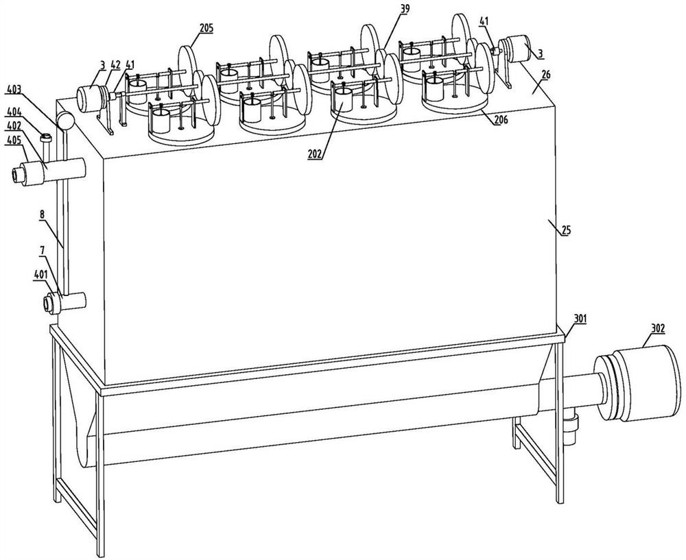
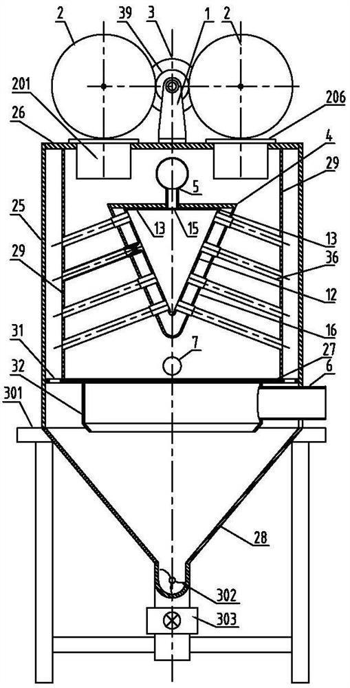
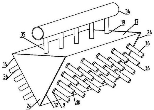
[0032] Embodiment 1: The present invention is used for cooling and waste heat power generation of furnace top gas with a temperature of 180°C, high content of superheated steam, dust, low-boiling point organic volatiles and a large amount of superheated steam. Components and each component is connected and assembled, adopting 8 low-temperature difference Stirling engines 2, two power generators 3 with a power of 10kw are respectively fixed on the two ends of the transmission shaft 37, and the height of the cylindrical shell 25 is 4 meters and wide. 3 meters and a length of 6 meters, the length of the air-flow uniform distribution device 4 is 5 meters, and the width is 1.2 meters. The inner diameter is 300mm, and the diameter of the cooling gas outlet pipe 6 is 250mm. When in use, the intake main pipe 34 (through the externally equipped hot gas valve) is connected to the furnace top gas, and the cooling gas outlet pipe 6 is connected to the outlet pipeline through the externally...


PUM


Abstract

The invention provides a hot flue gas purification and waste heat power generation integrated device. The hot flue gas purification and waste heat power generation integrated device comprises a steam generator for flue gas cooling, a transmission component, a Stirling engine and a power generator. The device has the effects that superheated steam in flue gas can be condensed to recycle sensible heat and latent heat in the flue gas, the effect that airflow in each heat exchange branch pipe is uniform is achieved through parts and the structure, and the device has the characteristics of being sufficient in waste heat recycling and high in heat exchange efficiency; and according to the device, the phenomenon that the heat exchange pipeline is blocked by fog drops generated by condensation of dust, low-boiling-point organic volatile matters, water vapor and the like in the heat exchange branch pipes can be reduced or avoided, meanwhile, the effect of removing some dust and condensate to purify flue gas is achieved, and the phenomena of cracking and steam leakage caused by thermal stress of connection points of different parts are reduced or avoided. According to a transmission component, power of the multiple Stirling engines is collected and then supplied to one generator, and the transmission component has the characteristics of being compact in equipment, small in occupied space, long in service life and good in safety.

Description

technical field [0001] The invention belongs to the technical field of energy and power, in particular to an integrated device for hot flue gas purification and waste heat power generation. Background technique [0002] At present, various kilns and combustion facilities produce a large amount of superheated steam, and at the same time contain dust and condensable volatiles, because the condensable volatiles contained in the cooling process condense droplets to block (heat exchange) pipes, so that The waste heat of the tail gas cannot be fully utilized. The existing technology usually uses several processes and several equipments in combination to cool the flue gas and recover the waste heat. There are many types, large space occupation, and large investment. If a method can be provided that can recover the sensible heat and latent heat in the flue gas during the flue gas cooling process, it can prevent the condensed droplets from clogging (heat exchange) pipes and improve t...

Claims


Application Information

Patent Timeline
Patent Type & Authority Applications(China)
IPC IPC(8): F27D17/00F28F17/00
CPCF27D17/004F27D17/008F28F17/005F27D2017/006Y02P10/25
Inventor 孙洵王振峰
Owner PULIN TAIYANG ZHENGZHOU ENERGY POWER
Why Eureka
Try Eureka