Large workpiece positioning and clamping system and method

A technology for positioning and clamping, large workpieces, applied in positioning devices, metal processing machinery parts, clamping, etc., can solve problems such as unrestricted excess degrees of freedom of workpieces, defective products with out-of-tolerance dimensions, and easy displacement of workpieces, etc., to achieve clamping Good holding effect, avoiding the interference of machining accuracy, and eliminating the effect of deformation

Pending Publication Date: 2021-11-16
中冶南方(武汉)重工制造有限公司
View PDF12 Cites 1 Cited by
  • Summary
  • Abstract
  • Description
  • Claims
  • Application Information

AI Technical Summary

Problems solved by technology

The traditional pressure plate and pad iron only limit the movement of the workpiece perpendicular to the support surface, while the rotation of the workpiece around the support surface is only limited by the friction force converted from the positive pressure applied on the pressure plate
This fixing method has the following problems: 1. The excess degree of freedom of the workpiece is not restricted, and the workpiece is prone to displacement; 2. Excessive positive pressure will cause the workpiece to deform, and for workpieces with poor rigidity, the size will be out of tolerance and produce defective products; 3. 1. The positive pressure exerted by the pressure plate needs to act on the upper surface of the workpiece. If the upper surface is the surface to be processed, the processing process will be interrupted; 4. In order to achieve sufficient pressing force, the operator needs to use a lever during the force application process. If there is insufficient space If it is allowed, it must be pressed with its own momentum; this way of working has potential safety hazards for both tools and personnel

Method used


Image

  • Large workpiece positioning and clamping system and method
  • Large workpiece positioning and clamping system and method
  • Large workpiece positioning and clamping system and method

Examples


Embodiment Construction

[0040] In order to better understand the present invention, the present invention will be further described below in conjunction with the accompanying drawings and specific embodiments.

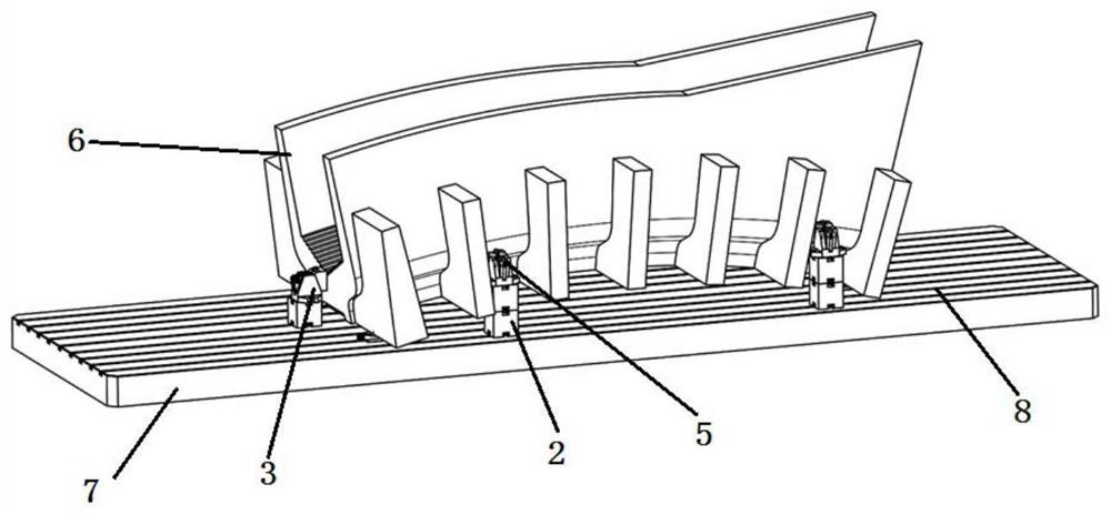
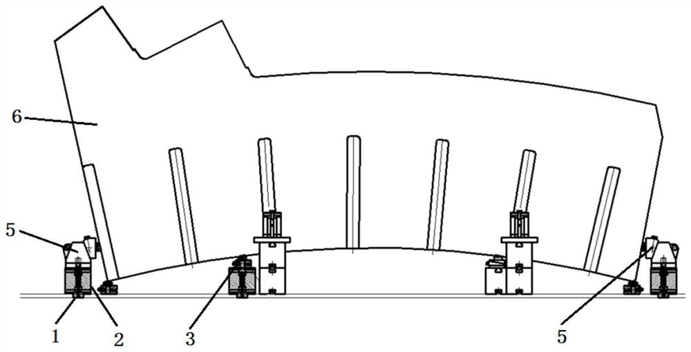
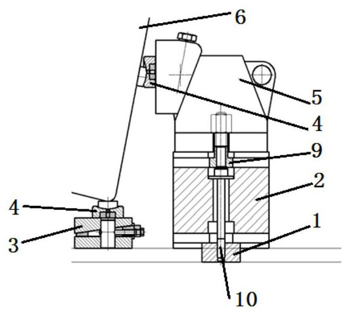
[0041] Such as Figure 1~3 A large workpiece positioning and clamping system shown includes a clamping platform 7, several adjustable parallel iron structures 3, several free vises 5 and spherical washers 4, and the adjustable parallel iron structures 3 are used for supporting and leveling The workpiece 6 is distributed around the workpiece 6 at circumferential intervals; a spherical washer 4 is installed on the top of the adjustable parallel iron structure 3, and the bottom of the adjustable parallel iron structure 3 is directly installed on the clamping platform 7, or by supporting The structure is installed on the clamping platform 7; the free vise 5 is used to apply pressure to the outer surface of the workpiece 6 to straighten the workpiece 6, and the free vise 5 is distributed around th...


PUM


Abstract

The invention discloses a large workpiece positioning and clamping system. The system comprises a clamping platform, a plurality of adjustable sizing block structures, a plurality of free vices and spherical washers, wherein the adjustable sizing block structures are used for supporting and leveling a workpiece and are circumferentially distributed around the workpiece at intervals; the spherical washers are mounted at the tops of the adjustable sizing block structures; the bottoms of the adjustable sizing block structures are directly mounted on the clamping platform or mounted on the clamping platform through a supporting structure; the free vices are used for applying pressure to the outer side surface of the workpiece so as to straighten the workpiece, the free vices are distributed around the workpiece at intervals in the circumferential direction, the free vices are directly mounted on the clamping platform or mounted on the clamping platform through the supporting structure, and the force application ends of the free vices are tightly pressed on the outer side surface of the workpiece through the spherical washers. The invention further provides a clamping method. The large workpiece positioning and clamping system has the beneficial effects that the free vices are matched with the adjustable sizing block structures, so that effective and reliable supporting and clamping force can be provided, and positioning and clamping of a large workpiece are achieved.

Description

technical field [0001] The invention relates to the technical field of mechanical processing, in particular to a large workpiece positioning and clamping system and method. Background technique [0002] Large workpieces need to be positioned and clamped on the machine tool before machining. The traditional pressure plate and pad iron only restrict the movement of the workpiece perpendicular to the abutment surface, while the rotation of the workpiece around the abutment surface is only limited by the friction force converted from the positive pressure applied on the pressure plate. This fixing method has the following problems: 1. The excess degree of freedom of the workpiece is not restricted, and the workpiece is prone to displacement; 2. Excessive positive pressure will cause the workpiece to deform, and for workpieces with poor rigidity, the size will be out of tolerance and produce defective products; 3. 1. The positive pressure exerted by the pressure plate needs to a...

Claims


Application Information

Patent Timeline
Patent Type & Authority Applications(China)
IPC IPC(8): B23Q3/06
CPCB23Q3/06
Inventor 李路
Owner 中冶南方(武汉)重工制造有限公司
Why Eureka
Try Eureka