
Linear oscillation motor sensorless control method and device

An oscillating motor and control method technology, which is applied in the direction of motor generator control, AC motor control, and electromechanical transmission control, can solve problems such as increasing system volume, reducing overall reliability, and difficult installation of position sensors, and achieves displacement estimation. High precision, weaken chattering problem, and improve the effect of displacement observation effect

Pending Publication Date: 2021-11-09
HUAZHONG UNIV OF SCI & TECH
View PDF2 Cites 3 Cited by
  • Summary
  • Abstract
  • Description
  • Claims
  • Application Information

AI Technical Summary

Problems solved by technology

[0005] Aiming at the defects of the prior art, the object of the present invention is to provide a position sensorless control method and device for a linear oscillating motor, which aims to solve the problem that the piston stroke of the linear oscillating motor is free and unrestricted, and if a position sensor is used to obtain Piston displacement information will not only increase the volume of the system and reduce the overall reliability, but also has the problem of difficult installation of the position sensor

Method used


Image

  • Linear oscillation motor sensorless control method and device
  • Linear oscillation motor sensorless control method and device
  • Linear oscillation motor sensorless control method and device

Examples


Embodiment

[0146] Taking the stator permanent magnet double-stator linear oscillation motor as an example, the above method is simulated and verified, and the rated power is set to 120W, the rated operating frequency is 22.1Hz, the stator resistance is 18.4Ω, the stator inductance is 0.755H, and the thrust coefficient is 47.08 N / A, the mass of the mover piston is 1.03kg.

[0147] Specifically, Fig. 4(a) and Fig. 4(b) respectively show the speed estimation signals obtained by the traditional open-loop back EMF method and the improved sliding mode observer method under the open-loop amplitude of the linear oscillator motor using a low-pass filter. Filtering results; from Figure 4(a) and Figure 4(b), it can be seen that the low-pass filter will cause displacement estimation signal amplitude and phase offset, and cannot solve the problem of sliding mode chattering; Figure 5(a) and Fig. 5(b) respectively show the traditional open-loop back EMF and the improved slippery current obtained by usi...


PUM


Abstract

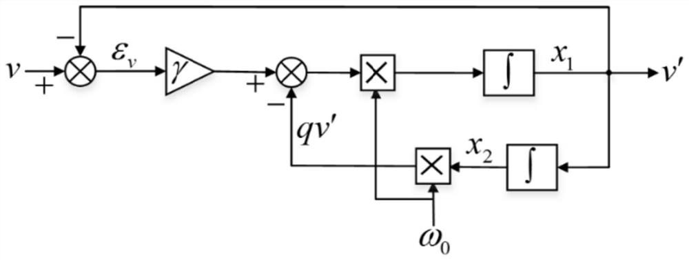
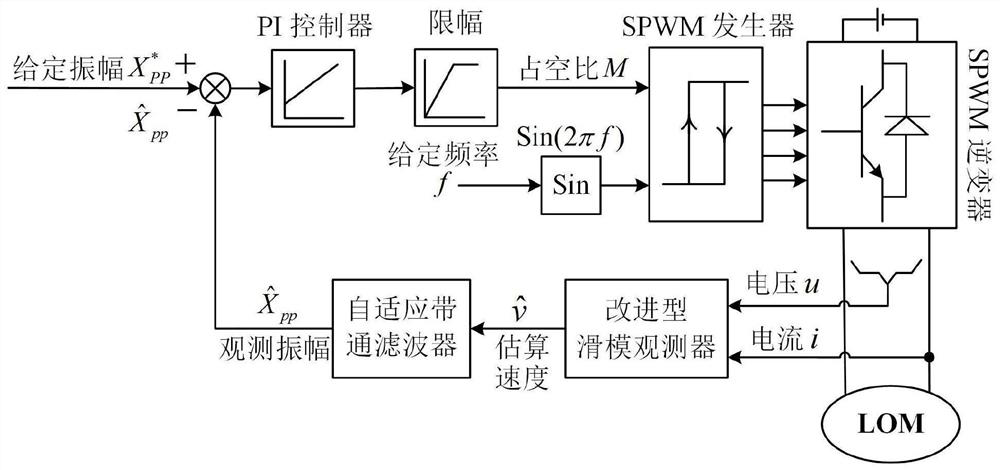
The invention provides a linear oscillation motor sensorless control method and device, which belong to the technical field of linear oscillation motor sensorless control. The method comprises the following steps of S1, sequentially carrying out the PI control operation and amplitude limiting of the difference between the current observation amplitude and the given amplitude, and obtaining the voltage duty ratio, S2, sequentially inputting the sine function with the given frequency and the voltage duty ratio into an SPWM generator and an SPWM inverter to obtain a modulation voltage signal, S3, collecting an output voltage signal and an output current signal of the linear oscillation motor, constructing a sliding mode observer, and obtaining an estimated speed of a piston, and S4, filtering the estimated speed to obtain a displacement observation signal, updating the current observation amplitude, and turning to the step S1. The sliding mode observer and the band-pass filter are adopted to replace a position sensor, and the problems that the size of a motor system is too large and the position sensor is difficult to install are solved.

Description

technical field [0001] The invention belongs to the technical field of position sensorless control of linear oscillating motors, and more specifically relates to a position sensorless control method and device for linear oscillating motors. Background technique [0002] Traditional compressors generally use a rotary motor, which uses a crank connecting rod structure to convert rotary motion into linear reciprocating motion, thereby driving the piston to move. This indirect drive mode using the intermediate transmission link to drive the motor has disadvantages such as complex structure, large volume, high noise and low efficiency. In addition, limited by the mechanical structure, the traditional compressor has the problem that the reciprocating stroke of the piston cannot be adjusted. The linear oscillating motor can directly realize the mutual conversion between electric energy and linear reciprocating mechanical energy. Compared with the traditional transmission method, i...

Claims


Application Information

Patent Timeline
Patent Type & Authority Applications(China)
IPC IPC(8): H02P21/14H02P21/13H02P21/18H02P21/22H02P21/24H02P25/032H02P25/06H02P27/12
CPCH02P21/0007H02P21/13H02P21/14H02P21/18H02P21/24H02P21/22H02P25/06H02P25/032H02P27/12
Inventor 徐伟廖凯举宫逸凡
Owner HUAZHONG UNIV OF SCI & TECH
Learn More