
Sewer detection and danger elimination system

A sewer and drainage hole technology, applied in the field of environmental protection detection and treatment equipment, can solve the problems of timely discharge of accumulated water, easy occurrence of deflagration, inconvenient discharge of accumulated water, etc., and achieves the effect of reducing urban waterlogging, improving safety, and increasing drainage.

Active Publication Date: 2021-11-09
深圳市博流测控技术有限公司
View PDF7 Cites 0 Cited by
  • Summary
  • Abstract
  • Description
  • Claims
  • Application Information

AI Technical Summary

Problems solved by technology

The gas in the sewer has a strong odor, and part of the gas is flammable. When the concentration of the flammable gas reaches a certain range, it is easy to deflagrate when encountering an open flame or high temperature, resulting in some safety accidents.
In addition, the sewer is generally arranged with a well, and the top of the well is equipped with a manhole cover with drainage holes. This kind of manhole cover cannot discharge the accumulated water in time when the precipitation is large, which will cause the water level to rise and cause waterlogging. If you want to increase the drainage It is necessary to manually lift the manhole cover to expose the well, but the operation of lifting the manhole cover is not convenient enough, and the labor intensity of manual operation is relatively high, which makes it inconvenient to discharge the accumulated water.

Method used


Image

  • Sewer detection and danger elimination system
  • Sewer detection and danger elimination system
  • Sewer detection and danger elimination system

Examples


Embodiment Construction

[0038] This part will describe the specific embodiment of the present invention in detail, and the preferred embodiment of the present invention is shown in the accompanying drawings. Each technical feature and overall technical solution of the invention, but it should not be understood as a limitation on the protection scope of the present invention.

[0039] In the description of the present invention, it should be understood that the orientation descriptions, such as up, down, front, back, left, right, etc. indicated orientations or positional relationships are based on the orientations or positional relationships shown in the drawings, and are only In order to facilitate the description of the present invention and simplify the description, it does not indicate or imply that the device or element referred to must have a specific orientation, be constructed and operated in a specific orientation, and thus should not be construed as limiting the present invention.

[0040] I...


PUM


Abstract

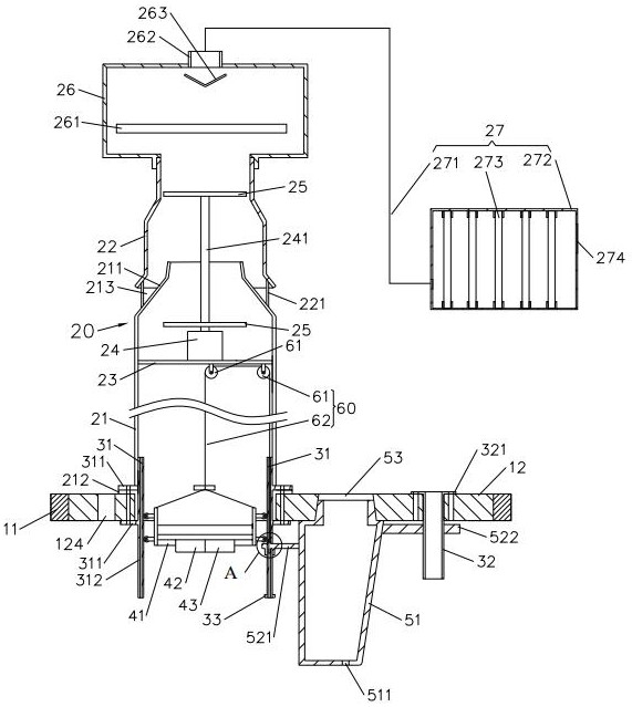
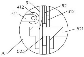
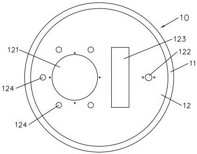
The invention discloses a sewer detection and danger elimination system. The sewer detection and danger elimination system comprises a well lid assembly, an exhaust device, a guide device, a detection device, a drainage device, a connecting device and a control device, wherein the well lid assembly comprises an outer frame and a well lid main body arranged on the inner side of the outer frame; the exhaust device comprises a first gas guide cylinder, a second gas guide cylinder, a first bracket, a motor, fan blades, a combustion bin and an absorption assembly; the guide device comprises a guide pipe fitting and a guide cylinder; the detection device comprises a second bracket, an ultrasonic ranging piece and a gas sensor; the drainage device comprises a water storage tank, a bracket assembly and a grating plate; the connecting device comprises a pulley arranged on the first bracket and a pull rope wound on the pulley; and the control device is arranged on the first gas guide cylinder or the second gas guide cylinder and is electrically connected with the motor, an igniter, the ultrasonic ranging piece and the gas sensor. Through the structure, the concentration of combustible gas can be detected, when the concentration exceeds the standard, gas in a sewer and a well can be pumped out, the combustible gas is combusted, toxic and harmful substances in waste gas are absorbed, and the safety is improved.

Description

technical field [0001] The invention relates to the field of environmental detection and processing equipment, in particular to a detection and elimination system for sewers. Background technique [0002] The internal environment of the sewer is usually poor, and there are sewage, sundries and many kinds of microorganisms inside, so that there will be toxic and harmful gases such as methane, hydrogen sulfide, and ammonia in the sewer. The gas in the sewer has a strong odor, and some of the gas is flammable. When the concentration of the flammable gas reaches a certain range, it is easy to deflagrate when encountering an open flame or high temperature, resulting in some safety accidents. In addition, the sewer is generally arranged with a well, and the top of the well is equipped with a well cover, and the well cover has drainage holes. This kind of well cover cannot discharge the accumulated water in time when the precipitation is large, which will cause the water level to r...

Claims


Application Information

Patent Timeline
IPC IPC(8): E03F5/06E03F5/10E03F5/24E03F7/00G01D21/02B01D53/04
CPCE03F5/06E03F5/10E03F5/24E03F7/00G01D21/02B01D53/04
Inventor 代兰李萌
Owner 深圳市博流测控技术有限公司
Learn More