
Magnetic separator with controllable magnetic force and for oil-water separation, and oil-water separation method thereof

A technology of oil-water separation and magnetic separation, which is applied in separation methods, magnetic field/electric field water/sewage treatment, liquid separation, etc. It can solve the problems of complex equipment, time-consuming and labor-consuming, and single treatment effect, and achieve the effect of simple and convenient operation

Pending Publication Date: 2021-11-09
TIANHUA INST OF CHEM MACHINERY & AUTOMATION
View PDF16 Cites 0 Cited by
  • Summary
  • Abstract
  • Description
  • Claims
  • Application Information

AI Technical Summary

Problems solved by technology

[0004] The magnetic separators that exist on the market often have a single treatment effect and low treatment efficiency. For example, the magnet in the sliding-separation magnetic separator whose publication number is CN107716104A is selected as a permanent magnet, and the fixed magnetic force that exists in it can only be used for sewage in a separate manner. Adsorption of a certain substance in the sewage cannot be done by other magnetic substances present in the sewage. Only permanent magnets can be replaced for adsorption, which is time-consuming and labor-intensive, and affects the treatment efficiency of sewage. Another example is a public number CN107552225A In this kind of magnetic separator, media boxes with different gradients are set to complete the adsorption of different magnetic substances. However, the equipment is complex and the treatment of sewage in the process of treatment only achieves the purpose of treatment through the time when sewage flows through the media box. The processing time The section leads to poor sewage treatment effect
In order to solve the above problems, the present invention provides a controllable magnetic oil-water separation magnetic separator and its oil-water separation method to solve the problem of low processing efficiency of the electromagnetic separator

Method used


Image

  • Magnetic separator with controllable magnetic force and for oil-water separation, and oil-water separation method thereof

Examples


Embodiment Construction

[0033] The following will clearly and completely describe the technical solutions in the embodiments of the present invention with reference to the accompanying drawings in the embodiments of the present invention. Obviously, the described embodiments are only some, not all, embodiments of the present invention. Based on the embodiments of the present invention, all other embodiments obtained by persons of ordinary skill in the art without making creative efforts belong to the protection scope of the present invention.

[0034] The object of the present invention is to provide a controllable magnetic force oil-water separation magnetic separator and its oil-water separation method to achieve the purpose of controlling the strength of the magnetic field and enhancing the efficiency of sewage treatment.

[0035] In order to make the above objects, features and advantages of the present invention more comprehensible, the present invention will be further described in detail below ...


PUM

PropertyMeasurementUnit
angleaaaaaaaaaa

Abstract

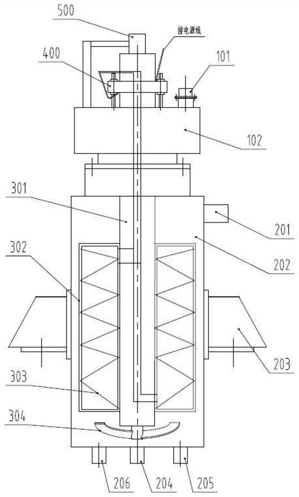
The invention discloses a magnetic separator with controllable magnetic force and for oil-water separation, and an oil-water separation method thereof. The magnetic separator comprises a shell provided with a feeding port and a discharging port and a rotating mechanism installed in the shell, wherein the rotating mechanism comprises a rotating shaft and blades installed in the circumferential direction of the rotating shaft, and magnetic-force-adjustable electromagnetic coils are installed in the blades. According to the invention, the electromagnetic coils are arranged in the blades and connected with a power source, and the magnetic force of the electromagnetic coils is controlled through the power source, so the surfaces of the blades are provided with magnetic fields of different sizes so as to realize attraction of oil and magnetic substances respectively; the oil and magnetic substances are released in sequence and discharged through a discharging port, so separation and collection of water, oil and the magnetic substances are completed; and the problem that separation efficiency is not high due to the fact that attraction equipment needs to be replaced when different substances are separated through an existing magnetic separator is solved.

Description

technical field [0001] The invention relates to the technical field of electromagnetic separation, in particular to a controllable magnetic force oil-water separation magnetic separator and an oil-water separation method thereof. Background technique [0002] Over the years, petroleum has been used as the driving force of industrial development. However, in the process of extensive use, petroleum pollution has become common. The post-treatment technology of petroleum pollution has become an international problem and a tough battle. [0003] As a new type of separation technology, magnetic separation technology has the advantages of high separation efficiency, large processing capacity, and low energy consumption. It has become the key direction of current and future research. [0004] The magnetic separators that exist on the market often have a single treatment effect and low treatment efficiency. For example, the magnet in the sliding-separation magnetic separator whose pu...

Claims


Application Information

Patent Timeline
Patent Type & Authority Applications(China)
IPC IPC(8): C02F1/48C02F1/40
CPCC02F1/48C02F1/40
Inventor 张万尧马天鑫孙中心张晓阳秦云龙冯小朋安丙峰郭雨王建刚梁元月张国海崔建航安亚中邱永宁吴炳珑
Owner TIANHUA INST OF CHEM MACHINERY & AUTOMATION
Learn More