Grinding equipment for front beam in rear floor front beam assembly and working method of grinding equipment

A front beam and rear floor technology, applied in grinding/polishing equipment, metal processing equipment, grinding workpiece support, etc. The effect of high feeding efficiency

Active Publication Date: 2021-11-09
合肥至信机械制造有限公司
View PDF11 Cites 5 Cited by
  • Summary
  • Abstract
  • Description
  • Claims
  • Application Information

AI Technical Summary

Problems solved by technology

[0003] The object of the present invention is to provide the front beam polishing equipment and working method thereof in the rear floor front beam assembly, and solve the following technical problems: (1) solve the grinding efficiency and The technical problem of low precision; (2) Solve the technical problem that waste debris is not easy to collect during the grinding process of the front beam in the rear floor front beam assembly in the prior art

Method used


Image

  • Grinding equipment for front beam in rear floor front beam assembly and working method of grinding equipment
  • Grinding equipment for front beam in rear floor front beam assembly and working method of grinding equipment
  • Grinding equipment for front beam in rear floor front beam assembly and working method of grinding equipment

Examples


Embodiment Construction

[0029] The following will clearly and completely describe the technical solutions in the embodiments of the present invention with reference to the accompanying drawings in the embodiments of the present invention. Obviously, the described embodiments are only some, not all, embodiments of the present invention. Based on the embodiments of the present invention, all other embodiments obtained by persons of ordinary skill in the art without creative efforts fall within the protection scope of the present invention.

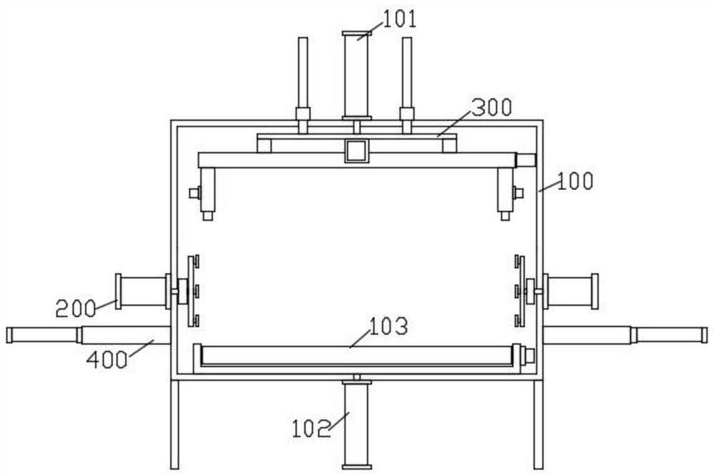
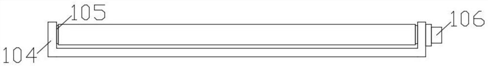
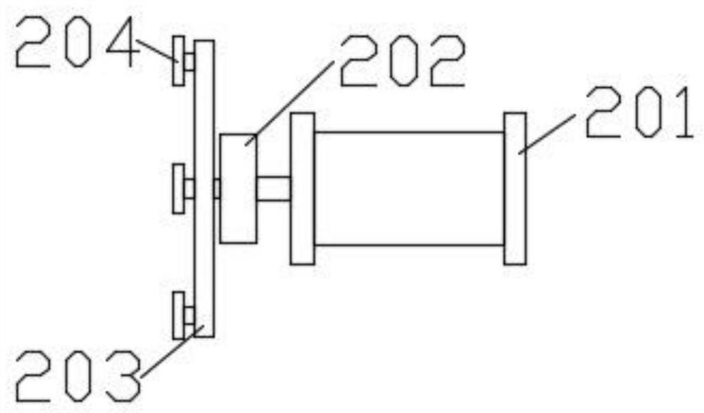
[0030] see Figure 1-8 As shown, the present invention is a polishing equipment for the front beam in the front beam assembly of the rear floor, including a grinding chamber 100, a limit mechanism 200 is installed on both sides of the grinding chamber 100, a lifting cylinder 101 is installed on the top of the grinding chamber 100 outer wall, and a lifting cylinder 101 The end of the piston rod is connected to the grinding mechanism 300, and the bottom of the outer ...


PUM


Abstract

The invention discloses grinding equipment for a front beam in a rear floor front beam assembly and a working method of the grinding equipment. The grinding equipment comprises a grinding chamber, wherein limiting mechanisms are installed on the two side walls of the grinding chamber correspondingly; a lifting cylinder is installed at the top of the outer wall of the grinding chamber; the end of a piston rod of the lifting cylinder is connected with a grinding mechanism; a jacking cylinder is installed at the bottom of the outer wall of the grinding chamber; the end of a piston rod of the jacking cylinder is connected with a conveying mechanism; and chip extraction mechanisms are installed on the outer walls of the two sides of the grinding chamber correspondingly. Through the arrangement of the conveying mechanism, the front beam in the rear floor front beam assembly can be conveyed, meanwhile, the front beam in the rear floor front beam assembly can be fed to the position between two rotating plates, the feeding efficiency is high, and through the arrangement of the chip extraction mechanisms, after feeding of the front beam in the rear floor front beam assembly is completed, two collecting boxes can automatically descend to the position below the front beam in the rear floor front beam assembly, and waste chips in the grinding process are efficiently collected.

Description

technical field [0001] The invention relates to the technical field of automobile processing, in particular to a front beam grinding device in a rear floor front beam assembly and a working method thereof. Background technique [0002] With the development of modern society, cars have become more and more common family transportation tools. The large and complex component structures in the car structure are simply replaced by a sheet metal part, which can reduce the process and process. The future development trend is the automobile The body can be assembled with only a few large sheet metal parts. Among them, the front beam in the rear floor front beam assembly is an important large-scale sheet metal part. However, the existing grinding equipment does not have high grinding efficiency and precision during the grinding process, and waste debris is not easy to collect during the grinding process. Contents of the invention [0003] The object of the present invention is to ...

Claims


Application Information

Patent Timeline
IPC IPC(8): B24B27/00B24B41/00B24B41/04B24B41/06B24B47/12B24B47/22B24B55/04B24B55/06B24B55/12
CPCB24B27/0076B24B41/005B24B41/04B24B41/06B24B55/04B24B47/22B24B47/12B24B55/06B24B55/12Y02P70/10
Inventor 任长记王松王祥保方岳丰苏承亮
Owner 合肥至信机械制造有限公司
Why Eureka
Try Eureka