Numerical control machine tool clamp capable of separating and collecting waste and water
A technology for CNC machine tools and waste materials, applied in clamping, manufacturing tools, maintenance and safety accessories, etc., can solve the problems of reducing the utilization rate of waste water, the water spray device does not have a collection function, and is inconvenient, and achieves the effect of increasing the utilization rate.
- Summary
- Abstract
- Description
- Claims
- Application Information
AI Technical Summary
Problems solved by technology
Method used
Image

Examples
Embodiment 1
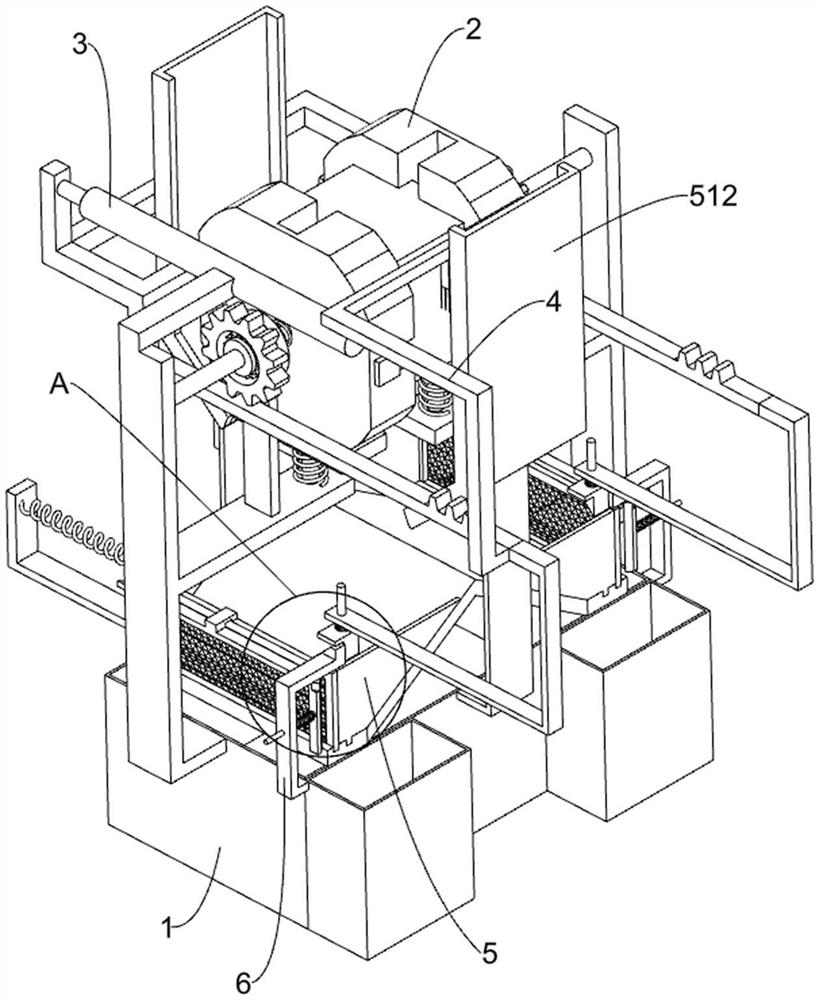
[0023] A CNC machine fixture that separates waste and water and collects them, such as Figure 1-3 As shown, it includes a first fixed frame 1, a clamping mechanism 2 and a rotating mechanism 3. The first fixed frame 1 is connected with a symmetrically rotating clamping mechanism 2. The clamping mechanism 2 is used to clamp the workpiece. The rotating mechanism 3 It is fixedly installed on the first fixed frame 1.
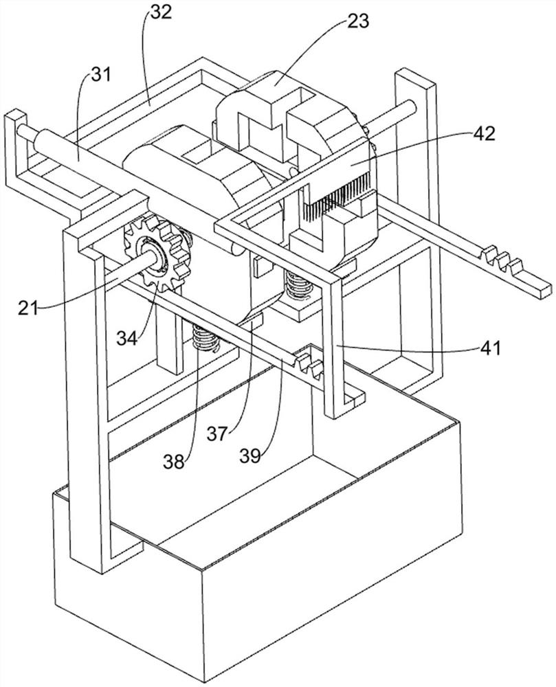
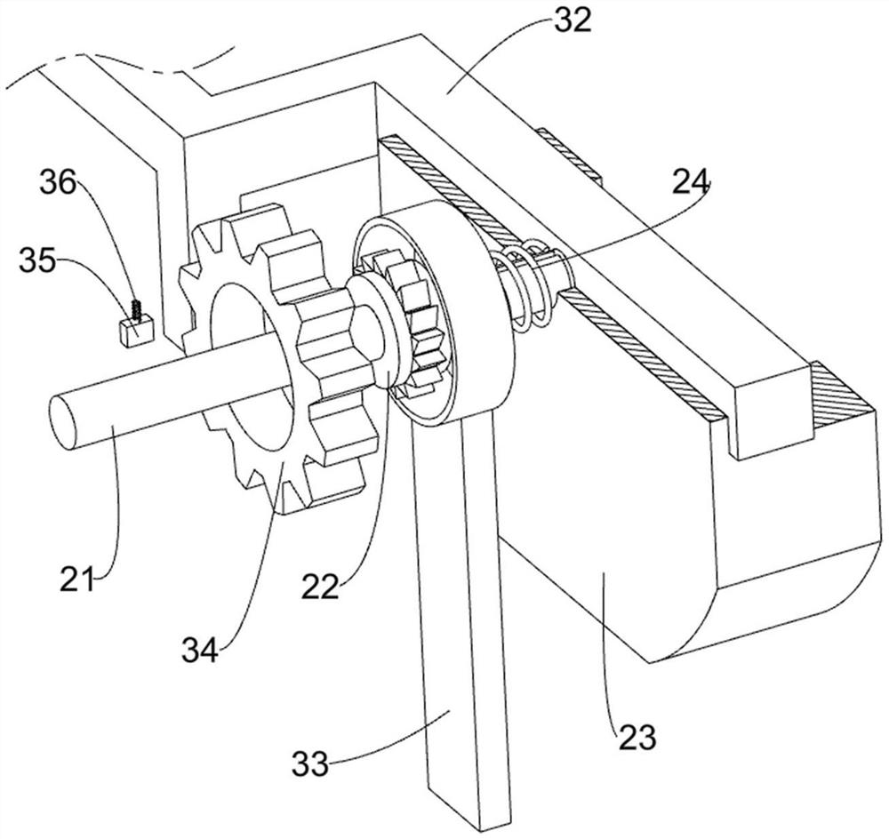
[0024] The clamping mechanism 2 includes a rotating shaft 21, a first gear 22, a clamping plate 23 and a first return spring 24. The rotating shaft 21 is connected with a symmetrical rotation on the first fixed frame 1, and a first rotating shaft is fixedly connected with the rotating shaft 21. The gear 22 and the clamping plate 23 are slidably connected to the rotating shaft 21 away from the first fixed frame 1, the clamping plate 23 is used to clamp the workpiece, and the first reset is connected between the first gear 22 and the clamping plate 23. Spring 24.
...
Embodiment 2
[0029] On the basis of Example 1, such as figure 2 As shown, a cleaning mechanism 4 is also included, and the cleaning mechanism 4 is arranged on one of the racks 39. The cleaning mechanism 4 is used to clean up the residual waste on the surface of the workpiece. The cleaning mechanism 4 includes a third fixed mount 41 And hairbrush 42, wherein a third fixed frame 41 is fixedly connected on one rack 39, and the third fixed frame 41 is provided with hairbrush 42, and hairbrush 42 is used for wiping the workpiece surface.
[0030] When the second fixed mount 32 and its upper device moved backward, the rack 39 would drive the brush 42 to move backward, and the brush 42 would wipe the surface of the workpiece to clean up the residual waste on the surface of the workpiece. When the second fixed mount 32 and its upper device moved forward, the rack 39 would drive the brush 42 to move forward, and the brush 42 would clean the dust on the other side of the workpiece.
Embodiment 3
[0032]On the basis of Example 2, such as Figure 4-5 As shown, a separation mechanism 5 is also included, and the separation mechanism 5 is arranged on the first fixed frame 1. The separation mechanism 5 is used to classify waste materials and waste water. The separation mechanism 5 includes a fourth fixed frame 51, a sliding frame 52, a filter screen 53. The fifth fixed frame 54, the fourth return spring 55, the sixth fixed frame 56, the wedge-shaped block 57, the fifth return spring 58, the wedge-shaped frame 59, the fixed frame 511 and the stop frame 512, fixedly installed on the first fixed frame 1 The fourth fixed frame 51 is arranged, and the symmetrical sliding type is connected with the sliding frame 52 on the fourth fixed frame 51, and the sliding frame 52 is used for pushing the waste into the fixed frame 511, and the sliding frame 52 is provided with a filter screen 53, and the filter screen 53 uses For filtering water, the filter screen 53 is slidingly connected wi...
PUM
 Abstract
Description
Claims
Application Information
 - R&D
- Intellectual Property
- Life Sciences
- Materials
- Tech Scout
- Unparalleled Data Quality
- Higher Quality Content
- 60% Fewer Hallucinations
Browse by: Latest US Patents, China's latest patents, Technical Efficacy Thesaurus, Application Domain, Technology Topic, Popular Technical Reports.
© 2025 PatSnap. All rights reserved.Legal|Privacy policy|Modern Slavery Act Transparency Statement|Sitemap|About US| Contact US: help@patsnap.com