
Folding massage bed with automatic bed bottom cleaning function

An automatic cleaning and folding technology, applied in vibration massage, carpet cleaning, floor cleaning, etc., can solve the problems of heavy workload of medical staff, poor experience of the people to be massaged, and large dust accumulation at the bottom of the bed, so as to improve the comfort of massage. , The effect of easy cleaning and comfortable neck

Inactive Publication Date: 2021-11-09
广东立曜工业有限公司
View PDF8 Cites 1 Cited by
  • Summary
  • Abstract
  • Description
  • Claims
  • Application Information

AI Technical Summary

Problems solved by technology

[0005] The purpose of the present invention is to provide a foldable massage bed with the function of automatically cleaning the bottom of the bed to solve the problem of the existing foldable massage bed proposed in the above background technology. A large amount of dust is often accumulated at the bottom of the bed, which requires manual cleaning. It is very strenuous, the massage table needs to turn over frequently to massage the face and back, which makes the experience of the massagers poor and the workload of the medical staff is heavy.

Method used


Image

  • Folding massage bed with automatic bed bottom cleaning function
  • Folding massage bed with automatic bed bottom cleaning function
  • Folding massage bed with automatic bed bottom cleaning function

Examples


Embodiment 1

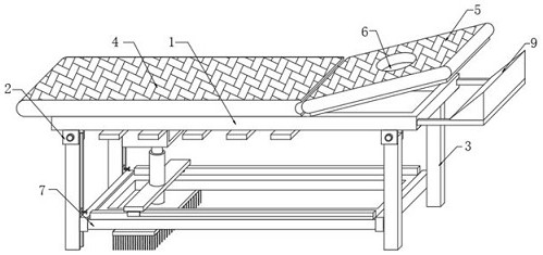
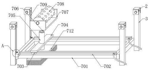
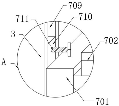
[0031] See 2- image 3 , in the embodiment of the present invention, the cleaning assembly 7 includes: a support frame 701 arranged under the bed frame 1, two electric control guide rails 702 are fixed on the upper end of the support frame 701, and electric sliding sleeves 703 are slidingly sleeved on the surface of the electric control guide rails 702; The connecting plate 704 at the upper end of the two electric sliding sleeves 703 is fixed with a sleeve 705 inside the connecting plate 704, and a cleaning brush 712 is fixed on the lower surface of the sleeve 705; The upper end surface is fixed with a C-shaped plate 707, and the inner cavity of the C-shaped plate 707 is horizontally rotated by a bearing to have a roller 708; 701 is fixedly connected to the slider 710, the internal thread of the slider 710 is engaged with a fastening bolt 711, and the fastening bolt 711 is connected with the inner cavity of the chute 709, and is used to fix the installation height of the slide...

Embodiment 2

[0033] see Figure 4-Figure 5The difference from Embodiment 1 is that the click assembly 8 includes: several support plates 801 fixed to the inner cavity of the bed frame 1 at equal distances in the horizontal direction, and several push rods 802 are inserted through the interior of the several support plates 801 , and several push rods 802 The upper end of the push rod 802 is fixed with a little press head 805; and the top plate 803 fixed on the lower end of several push rods 802, the first spring 804 is fixed between the top plate 803 and the lower end surface of the bed frame 1, and the top plate 803 is set opposite to the roller 708 for Squeeze the click head 805 to move upwards, the roller 708 rotates and squeezes several top plates 803, several top plates 803 can drive the click head 805 to move upward, and the click head 805 can squeeze the mattress 4, making the mattress 4 It can be squeezed to form a bulge, thereby being able to squeeze the acupoints of the person to ...

Embodiment 3

[0035] see Figure 6 The difference from Embodiment 1 is that the headrest assembly 9 includes: two inner rods 901 socketed on one side of the bed frame 1, and a cushion box 902 is fixed on the upper end surface of the inner rods 901; A vibrating plate 903, a vibrating motor 904 is fixed on the lower end of the vibrating plate 903; The inner tube 907 socketed in the inner cavity of 905, the inner tube 907 is fixedly installed with the lower end of the vibrating plate 903, the vibrating plate 903 is arranged opposite to the head pad 5, and is used to make the head pad 5 vibrate, and the end of the bed frame 1 close to the inner rod 901 is equipped with a spring latch , The surface of the inner rod 901 is provided with a plurality of aligning grooves, when the spring pin snaps into the aligning grooves, the inner rod 901 can be fixed.

[0036] The working principle of the present invention is: first place the massage bed at a designated position, and by manually rotating the fo...


PUM


Abstract

The invention discloses a folding massage bed with an automatic bed bottom cleaning function. The folding massage bed comprises a bed frame, folding rotating pieces fixed on the periphery of the lower end of the bed frame, a mattres placed on one side of the upper end face of the bed frame, a cleaning assembly arranged at the lower end of the bed frame and a point pressing assembly arranged in an inner cavity of the bed frame, and supporting columns are fixed at the rotating ends of the folding rotating pieces; and a headrest is placed on the other side of the upper end face of the bed frame, and a ventilation through opening is formed in the headrest. According to the folding massage bed with the automatic bed bottom cleaning function, under the action of the cleaning assembly, sliding grooves formed in the surfaces of the supporting columns can sleeve the supporting frame through sliding blocks, so that the stability of the folding bed is improved; and meanwhile, when an electric sliding sleeve reciprocates on the surface of an electric control guide rail, a cleaning brush and a roller can be driven to reciprocate, the cleaning brush can sweep the bottom of the bed, the traditional manual cleaning mode is changed, the cleaning operation is easier, the returning roller can extrude the point pressing assembly to perform the point pressing operation, and the massage comfort is improved.

Description

technical field [0001] The invention relates to the field of massage bed equipment, in particular to a foldable massage bed with the function of automatically cleaning the bottom of the bed. Background technique [0002] Massage is based on the theory of viscera and meridians of traditional Chinese medicine, combined with the anatomy and pathological diagnosis of western medicine, and uses techniques to act on specific parts of the human body surface to adjust the physiological and pathological conditions of the body and achieve the purpose of physical therapy. It is said that it is a physical therapy method. From the perspective of massage therapy, it can be divided into health massage, sports massage and medical massage. During massage, it is necessary to wait for the massage personnel to lie on the bed, and professional massage medical staff will perform manual massage operations. [0003] The existing folding massage bed, in the process of its use, often accumulates a la...

Claims


Application Information

Patent Timeline
Patent Type & Authority Applications(China)
IPC IPC(8): A61G13/00A61G13/10A61G13/12A61H23/02A61H7/00A61H39/04A47L11/24A47L11/40
CPCA61G13/009A61G13/121A61G13/10A61H23/02A61H39/04A61H7/001A47L11/24A47L11/40A47L11/4036A47L11/4069A61H2201/0142
Inventor 王宗连
Owner 广东立曜工业有限公司
Learn More