
Integrated guide rail distribution switching power supply topology based on LCL compensation

A compensation topology and capacitor compensation technology, applied in charging stations, electric vehicles, electrical components, etc., can solve problems such as cost increase, easy-to-burn devices, breakdown capacitors or switch tubes, etc., to reduce volume and cost, and reduce control difficulty , The effect of reducing the electrification length

Pending Publication Date: 2021-11-02
HARBIN INST OF TECH
View PDF0 Cites 0 Cited by
  • Summary
  • Abstract
  • Description
  • Claims
  • Application Information

AI Technical Summary

Problems solved by technology

This method has a simple structure and low cost, but requires more power supply lines and longer lengths, and the switch is in a hard switching state, which is easy to burn the device, and it is difficult to open two sections of guide rails at the same time
②The multi-source independent power supply scheme refers to the provision of a transmitting power supply for each section of the power supply rail. This method eliminates the switch, simple structure, and easy switching, but the number of power supplies is too large and the cost is high
③The multi-source hybrid power supply scheme is an improvement on the single-source segmented power supply, which reduces the number of segments driven by each power supply rail to reduce the pressure on a single power supply, but the problem of hard switching and simultaneous power supply of two-segment rails has not yet been solved locally
④The multi-source hybrid alternate power supply scheme adopts two power supplies alternately connected to the launch rails, while reducing the number of power supplies, it allows two adjacent sections of the rails to work at the same time, which reduces costs and improves the stability of the received power, but there is still a problem with the power supply line. Long, limited rail length for single-supply drive and disadvantages of hard switching
However, the LCL compensation topology needs to be matched with a compensation inductor whose inductance and current resistance are equivalent to those of the launch rail. This inductor has a large volume and introduces more losses, which increases the cost and reduces the system efficiency.
And there is a closed resonant circuit, the voltage induced in the non-working state will generate a large current, and there is a hidden danger of breakdown capacitors or switch tubes
[0006] In summary, for the dynamic wireless power supply system transmitter power supply rail, the segmented arrangement and switching method that is low cost, high efficiency, online soft switching, multi-load compatible and can reduce the difficulty of power supply design needs to be further studied

Method used


Image

  • Integrated guide rail distribution switching power supply topology based on LCL compensation
  • Integrated guide rail distribution switching power supply topology based on LCL compensation
  • Integrated guide rail distribution switching power supply topology based on LCL compensation

Examples


Embodiment Construction

[0045] The technical solutions in the embodiments of the present invention will be clearly and completely described below in conjunction with the accompanying drawings in the embodiments of the present invention. Obviously, the described embodiments are only some of the embodiments of the present invention, not all of them; based on this The embodiments in the invention, and all other embodiments obtained by persons of ordinary skill in the art without creative efforts, all belong to the scope of protection of the present invention.

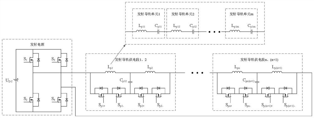
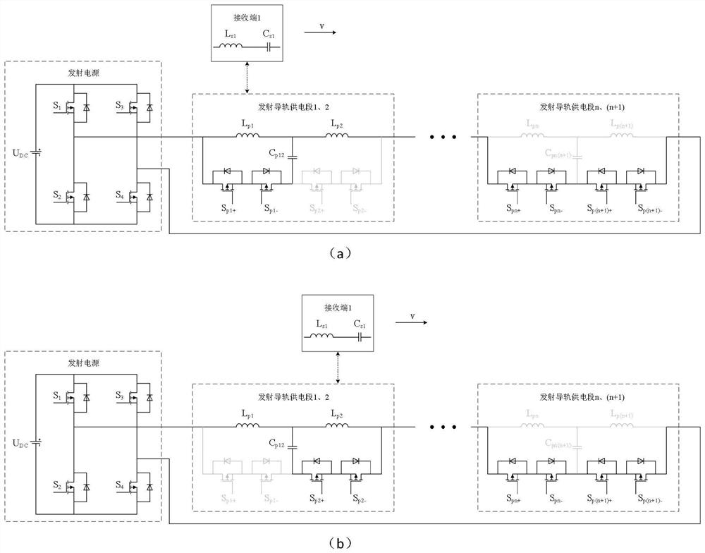
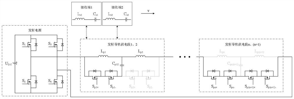
[0046] An integrated rail distributed switching power supply topology based on LCL compensation: such as figure 1 , wherein the minimum unit constituting the dynamic wireless power supply launch rail is the launch rail unit;

[0047] The power supply topology includes a launch power supply and n sections of launch rail power supply sections;

[0048] The transmitting power supply includes a constant voltage bus U DC and 4 switching tubes S 1 ,...


PUM


Abstract

The invention provides an integrated guide rail distribution switching power supply topology based on LCL compensation. The power supply topology comprises an emission power supply and n emission guide rail power supply sections; the emission power supply comprises a constant voltage bus UDC and four switch tubes; each of the n emission guide rail power supply sections comprises an LCL compensation topology and two groups of switching tubes Spn+ and Spn- which are connected in series reversely; the LCL compensation topology is composed of two adjacent emission guide rails Lpn and Lp(n+1) and a parallel compensation capacitor Cpn(n+1); the emission guide rail Lpn is formed by connecting an emission coil Lpnm and a compensation capacitor Cpnm integrated in the emission coil Lpnm in series; the switch tubes Spn+ and Spn- are connected in parallel at two sides of a branch formed by two adjacent sections of transmitting guide rails Lpn and Lp(n+1) and the parallel compensation capacitor Cpn(n+1); the multiplexing emission guide rail power supply section compensates for the adjacent power supply sections, and there is no need to configure a compensation inductor for each power supply section; the multiplexing resonant capacitor compensates for the two power supply sections, so that the number of capacitors is reduced; and due to high multiplexing of the system, the number of resonators is reduced, the size and cost of the system are reduced, loss is reduced, and the efficiency of the system is improved.

Description

technical field [0001] The invention belongs to the field of wireless energy transmission and dynamic wireless power supply, and in particular relates to an integrated guide rail distributed switching power supply topology based on LCL compensation. Background technique [0002] Dynamic wireless power supply technology can supplement electric energy in real time during the driving of electric vehicles, so it can increase the cruising range, reduce the ratio of power batteries, and overcome the disadvantages of traditional wired charging methods, which has important research value. At present, it is constantly developing in the direction of high power, long distance and long mileage. The research on dynamic wireless power supply technology at home and abroad is mainly carried out around the long guide rail type and multi-coil arrangement type magnetic coupling mechanism. In terms of its own structure and characteristics, magnetic core configuration, coupling performance chara...

Claims


Application Information

Patent Timeline
Patent Type & Authority Applications(China)
IPC IPC(8): H02J50/12B60L53/12
CPCH02J50/12B60L53/12Y02T10/70Y02T10/7072Y02T90/14
Inventor 崔淑梅高鑫杜博超程远
Owner HARBIN INST OF TECH
Learn More