
Miniature simulation synchronous phase modifier control system and working method thereof

A technology for simulating synchronization and control systems, applied in system integration technology, information technology support systems, AC network voltage adjustment, etc., can solve the problems of low accuracy and intuition of experimental results.

Pending Publication Date: 2021-11-02
RES INST OF ECONOMICS & TECH STATE GRID SHANDONG ELECTRIC POWER +1
View PDF0 Cites 0 Cited by
  • Summary
  • Abstract
  • Description
  • Claims
  • Application Information

AI Technical Summary

Problems solved by technology

[0005] This application provides a micro-analog synchronous condenser control system and its working method to solve the problem that the accuracy of the experimental results obtained by the synchronous condenser simulation method in the prior art is low and not intuitive enough

Method used


Image

  • Miniature simulation synchronous phase modifier control system and working method thereof
  • Miniature simulation synchronous phase modifier control system and working method thereof
  • Miniature simulation synchronous phase modifier control system and working method thereof

Examples


Embodiment 1

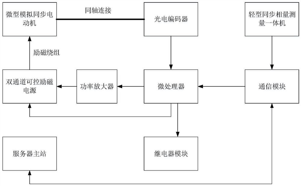
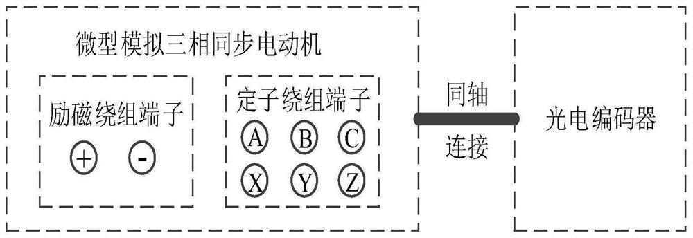
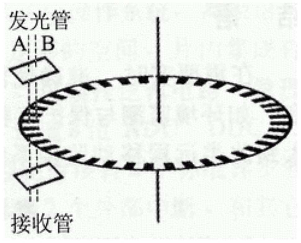
[0046] see figure 1 , figure 1 It is a schematic structural diagram of a micro analog synchronous condenser control system provided by the embodiment of the present application. Depend on figure 1 It can be seen that the micro-analog synchronous condenser control system in this embodiment mainly includes: a micro-analog synchronous motor, a photoelectric encoder, a light-duty synchrophasor measurement integrated machine, a microprocessor, a power amplifier, a dual-channel controllable excitation power supply, and a communication module , relay module and server master station. The miniature analog synchronous motor is coaxially connected with the photoelectric encoder, the photoelectric encoder is connected with the microprocessor through two data lines, the microprocessor is connected with the light synchrophasor measurement integrated machine through the communication module, and the communication module also communicates with the server master station connection, the mic...

Embodiment 2

[0094] exist Figure 1-Figure 11 Based on the example shown see Figure 12 , Figure 12 It is a schematic flowchart of a working method of a micro analog synchronous condenser control system provided by the embodiment of the present application.

[0095] Depend on Figure 12 It can be seen that the working method of the micro analog synchronous condenser control system in this embodiment mainly includes the following steps:

[0096] S1: Using a miniature analog synchronous motor to simulate a synchronous condenser in a real power system.

[0097] S2: According to the obtained monitoring command, the speed of the miniature analog synchronous motor is monitored in real time.

[0098] That is, according to the command of the server master station, the monitoring is started.

[0099] S3: According to the obtained control command, by adjusting the excitation input voltage, control the running state, reactive power output value and reactive power absorption value of the micro a...


PUM


Abstract

The invention discloses a miniature simulation synchronous phase modifier control system and a working method thereof. The system comprises a miniature simulation synchronous motor, a photoelectric encoder, a light synchronous phasor measurement all-in-one machine, a microprocessor, a power amplifier, a dual-channel controllable excitation power supply, a communication module, a relay module and a server master station. The method comprises the following steps of: simulating a synchronous phase modifier by using the miniature simulation synchronous motor; monitoring a rotating speed of the miniature simulation synchronous motor; controlling an operation state, a reactive power output value and a reactive power absorption value of the miniature simulation synchronous motor by adjusting the excitation input voltage, and calculating to obtain synchronous phasor data; uploading the synchronous phasor data to the server master station, and receiving, checking and analyzing the synchronous phasor data in a multi-thread mode; and adjusting the output power and the power factor of the miniature simulation synchronous motor. According to the miniature simulation synchronous phase modifier control system and the working method thereof, real-time monitoring of the miniature simulation synchronous phase modifier can be realized, and the control precision and the experiment intuition are improved.

Description

technical field [0001] The present application relates to the technical field of synchronous condenser simulation, in particular to a control system of a miniature analog synchronous condenser and its working method. Background technique [0002] The synchronous condenser is also called the synchronous compensation machine. It operates in the state of the motor, without mechanical load and without prime mover drive. It can be regarded as only absorbing a small amount of active power from the power system to maintain operation, and according to the needs of the system, to the A synchronous motor that supplies or absorbs reactive power in a power system. Synchronous condensers are widely used in power system operation and control due to their smooth adjustment process, no reduction in system inertia, flexible over-excitation / under-excitation switching, large reactive power compensation power, and mature production and maintenance technologies. Therefore, the development prosp...

Claims


Application Information

Patent Timeline
IPC IPC(8): H02J3/18H02J3/16H02J13/00H02H7/26
CPCH02J3/18H02J3/16H02J13/00016H02J13/00028H02J13/00001H02H7/26Y02E40/30Y02E40/70Y02E60/00Y02B90/20Y04S10/22Y04S40/124
Inventor 李昊鉴庆之李文升王春义赵龙张晓磊郑志杰贾善杰梁荣杨波卢志鹏吴奎华朱毅
Owner RES INST OF ECONOMICS & TECH STATE GRID SHANDONG ELECTRIC POWER
Learn More