Eureka AIR delivers breakthrough ideas for toughest innovation challenges, trusted by R&D personnel around the world.

Display panel and display device

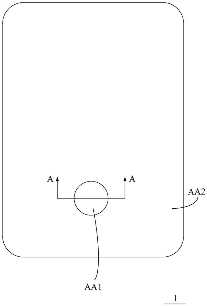
A technology of display panel and display area, applied in the direction of electrical components, diodes, electric solid-state devices, etc., can solve the problems affecting the display effect of the display panel and the difference in display brightness, and achieve uniform display effect, eliminate brightness differences, and reduce performance differences. Effect

Pending Publication Date: 2021-11-02
HEFEI VISIONOX TECH CO LTD
View PDF0 Cites 0 Cited by
  • Summary
  • Abstract
  • Description
  • Claims
  • Application Information

AI Technical Summary

Problems solved by technology

[0002] The organic light-emitting diode display panel (OLED) has the characteristics of self-luminescence and thinning. The display panel includes a first display area and a second display area. In the display panel, a light-shielding layer is formed on the side of the array substrate away from the light-emitting surface. The light-shielding layer is connected with the first display area. A light-transmitting part is formed at a position opposite to the display area, so that the light passes through the light-transmitting part to the photosensitive module arranged on the side of the display panel away from the light-emitting surface, but when the display panel displays, the first display corresponding to the light-transmitting part There will be a difference in display brightness between the second display area and the second display area without a light-transmitting part, which will affect the display effect of the display panel

Method used


Image

  • Display panel and display device
  • Display panel and display device
  • Display panel and display device

Examples


Embodiment Construction

[0039]Features and exemplary embodiments of various aspects of the present application will be described in detail below. In the following detailed description, numerous specific details are set forth in order to provide a thorough understanding of the application. It will be apparent, however, to one skilled in the art that the present application may be practiced without some of these specific details. The following description of the embodiments is only to provide a better understanding of the present application by showing examples of the present application.

[0040] It should be noted that in this article, relational terms such as first and second are only used to distinguish one entity or operation from another entity or operation, and do not necessarily require or imply that there is a relationship between these entities or operations. There is no such actual relationship or order between them. Furthermore, the term "comprises", "comprises" or any other variation the...


PUM


Abstract

The embodiment of the invention discloses a display panel and a display device. The display panel comprises a display function layer which comprises an array substrate and a light-emitting element layer formed on the array substrate; a shading layer is formed on the side, away from the light-emitting element layer, of the array substrate, and the shading layer is provided with a light-transmitting part in a first display area; a light regulation and control layer is formed on the side, away from the light emitting face of the display panel, of the display function layer, the orthographic projection of the light regulation and control layer on the shading layer covers the light-transmitting part, the light regulation and control layer comprises an electromagnetic switch assembly, and the electromagnetic switch assembly comprises a first polarity piece, a second polarity piece and an induction piece located between the first polarity piece and the second polarity piece; and the deflection amount of the induction piece is controlled through electromagnetic field flux generated between the first polarity piece and the second polarity piece, so that the induction piece is switched between a shading station and a light-transmitting station. The display panel is uniform in display brightness and good in user experience.

Description

technical field [0001] The present application relates to the technical field of electronic products, in particular to a display panel and a display device. Background technique [0002] The organic light-emitting diode display panel (OLED) has the characteristics of self-luminescence and thinning. The display panel includes a first display area and a second display area. In the display panel, a light-shielding layer is formed on the side of the array substrate away from the light-emitting surface. The light-shielding layer is connected with the first display area. A light-transmitting part is formed at a position opposite to the display area, so that the light passes through the light-transmitting part to the photosensitive module arranged on the side of the display panel away from the light-emitting surface, but when the display panel displays, the first display corresponding to the light-transmitting part There will be a difference in display brightness between the second...

Claims


Application Information

Patent Timeline
Patent Type & Authority Applications(China)
IPC IPC(8): H01L27/32
CPCH10K59/50
Inventor 张幸福
Owner HEFEI VISIONOX TECH CO LTD
Why Eureka
Eureka Blog
Learn More