
Terminal sheath and terminal connector

A terminal and sheath technology, which is applied in the field of terminal sheaths and terminal connectors, can solve the problems of insufficient withstand voltage, large installation space, short circuit, etc., to improve the withstand voltage protection performance, avoid protruding, and reduce costs Effect

Pending Publication Date: 2021-11-02
黄帅
View PDF0 Cites 0 Cited by
  • Summary
  • Abstract
  • Description
  • Claims
  • Application Information

AI Technical Summary

Problems solved by technology

[0002] At present, with the miniaturization of relays, the inserts (relay terminals) of the relay itself are relatively compact, but most of the mating connectors that are connected to the inserts are exposed, which makes it easy to form a gap between the two inserts. Short circuit, or insufficient voltage resistance, can easily damage electrical appliances
[0003] In addition, even if there are sheaths outside some mating terminals, the volume of the existing sheaths is large, resulting in a large installation space, which in turn requires a high installation space, and it is difficult to meet the needs of miniaturization of relays.

Method used


Image

  • Terminal sheath and terminal connector
  • Terminal sheath and terminal connector
  • Terminal sheath and terminal connector

Examples


Embodiment 1

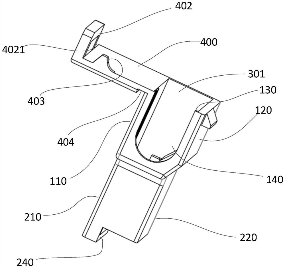
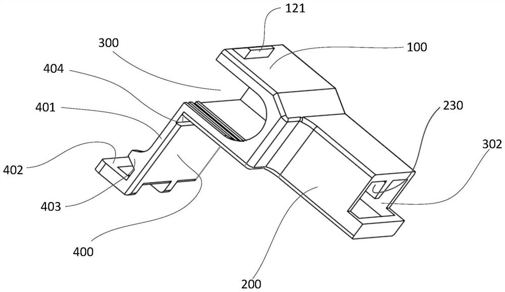
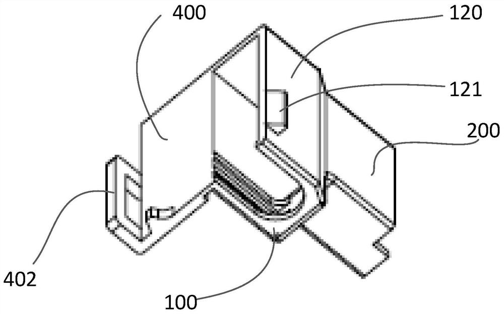
[0045] see Figure 1 to Figure 7, The present embodiment provides a terminal sheath 1. The present invention discloses a relay for providing insulation protection for terminals, a micro switch, a heating rod, a boat switch, and a terminal sheath for PCBA6.3 / 4.8 sockets. Specifically, the terminal sheath is suitable for the insulation protection of relay terminals for plug-in assembly. More specifically, the terminal sheath is suitable for but not limited to (American standard) 250 / 187 relay inserts, or 6.3, 4.8 and other (successful standard) relay inserts.

[0046] The terminal sheath 1 includes: a main body. Wherein, the main body has an inlet 301 and an inlet 302 facing away from each other. The main body has a through hole 300 communicating with the inlet 301 and the socket 302 . The through hole 300 extends lengthwise. The inlet 301 is used for inserting the terminal 2 into the through hole 300 of the main body to form a terminal connector. The pair of sockets 302 ar...

Embodiment 2

[0062] see Figure 8 to Figure 11 , an embodiment of the present application is a terminal sheath. Among them, such as Figure 7 As shown, the mating terminal has a flag-shaped structure. The mating terminal has a sheet body, a groove wall disposed on the sheet body and protruding from the sheet body, and a groove portion defined by the groove wall. The sheet body is a metal sheet body. The groove wall is formed by winding the side of the sheet. Of course, in other embodiments, the groove wall may also be a stamped protrusion on the sheet. A groove is formed between the groove walls on both sides of the sheet. The groove wall is formed on the sheet body, and one end of the sheet body is provided with a connecting end connected with the cable. The other end of the sheet is free and inserted into the terminal shield. The groove wall and the groove portion extend between the free end and the connection end. The end of the groove wall close to the connecting end is the top...


PUM


Abstract

The invention discloses a terminal sheath for providing insulation protection for a terminal, and a terminal connector. According to the invention, the terminal of plug-in connectors is provided with a sheet body, a groove wall which is arranged on the sheet body and protrudes out of the sheet body, and a groove part which is defined by the groove wall. The terminal sheath comprises a main body made of an insulating material, wherein the main body is provided with a through hole penetrating through the main body in an axial direction; two ends of the through hole are respectively provided with a feeding port and a plugging port; the feeding port is used for inserting the terminal of plug-in connectors into the through hole along the axial direction; the plugging port is used for inserting a plugging sheet into the through hole so as to realize electric connection between the plugging sheet and the terminal of plug-in connectors; the main body is also provided with a cover plate which is used for fixedly covering the feeding port, and a threading hole which is used for allowing a cable connected with the terminal of plug-in connectors to pass through; and the main body is further provided with a limiting buckle part protruding towards the interior of the through hole, and the limiting buckle part can be buckled on one side, far away from the plugging port, of the groove wall to axially limit the terminal of plug-in connectors.

Description

technical field [0001] The invention relates to a terminal sheath and a terminal connector, in particular to a terminal sheath suitable for but not limited to 250 relays. Background technique [0002] At present, with the miniaturization of relays, the inserts (relay terminals) of the relay itself are relatively compact, but most of the mating connectors that are connected to the inserts are exposed, which makes it easy to form a gap between the two inserts. Short circuit, or insufficient voltage resistance, can easily damage electrical appliances. [0003] In addition, even if there are sheaths outside some mating terminals, the existing sheaths are large in size, resulting in a large installation space, which in turn requires a high installation space, and it is difficult to meet the needs of miniaturization of relays. Contents of the invention [0004] In order to solve the above problems, the present invention provides a terminal sheath and a terminal connector that p...

Claims


Application Information

Patent Timeline
Patent Type & Authority Applications(China)
IPC IPC(8): H01H45/14H01R13/40
CPCH01H45/14H01R13/40
Inventor 黄帅
Owner 黄帅
Learn More