Durable cable
A kind of cable and durable technology, applied in the field of durable cables, can solve the problems of tensile strength, heat dissipation, waterproof and other performance needs to be improved, poor cable durability, cable damage and other problems, to improve the compression protection performance, the structure is strong, and the compression protection is guaranteed. Effect
- Summary
- Abstract
- Description
- Claims
- Application Information
AI Technical Summary
Problems solved by technology
Method used
Image
Examples
Embodiment 1
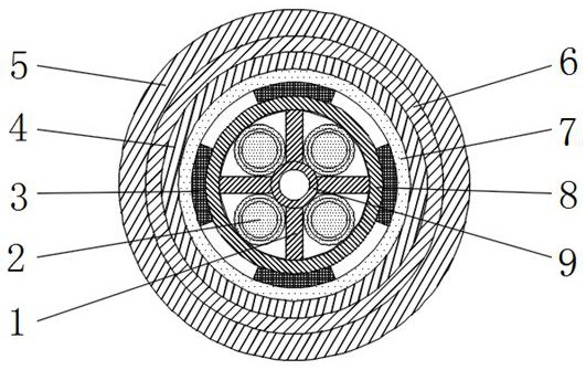
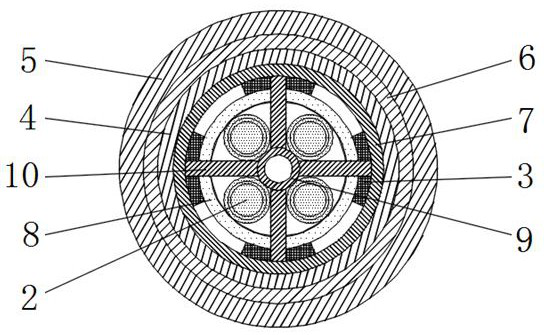
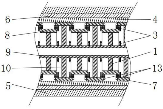
[0040] Such as Figure 1-3The shown durable cable includes a cable core, a protective layer and an outer sheath 5 arranged sequentially from the inside to the outside. The outer sheath 5 is made of EPDM rubber, which has excellent Weather resistance, ozone resistance, heat resistance, acid and alkali resistance, water vapor resistance and other properties, so that it can play a variety of protective functions on the surface of the cable. At least two wire cores 2 (in this embodiment, there are Four wire cores 2), the wire core 2 includes a conductor, an insulating layer and a shielding layer arranged in sequence from inside to outside, and the protective layer includes a waterproof layer 4 and an armor layer 6 arranged outside the waterproof layer 4. The waterproof protection of the cable core can be enhanced through the waterproof layer 4; the strength of the power cable can be improved through the armor layer 6, and the radial pressure bearing performance of the power cable c...
Embodiment 2
[0049] The difference between this embodiment and embodiment 1 is:
[0050] In this example, if Figure 6 As shown, a circle of support blocks 3 equally spaced is provided on the outer ring surface of each of the small ring sleeves 8 , and both ends of the support blocks 3 extend beyond the end surfaces of the corresponding sides of the small ring sleeves 8 . Only one circle of support block 3 is arranged on the outside of each small ring sleeve 8, and the two ends of the support block 3 are respectively connected to the large ring sleeve 7 and the small ring sleeve 8 on both sides, which can meet the design requirements and facilitate support Block 3 installation.
[0051] In this example, if Figure 4-6 As shown, in each adjacent small ring sleeve 8 and large ring sleeve 7, the short support bars 1 and the long support bars 10 correspond one-to-one, and the short support bars 1 and the long support bars 10 are misplaced. The short support bars 1 and the long support bars ...
Embodiment 3
[0054] The difference between this embodiment and embodiment 2 is:
[0055] In this example, if Figure 7 As shown, in the same annular gap, the structure of the support block 3 is fan-shaped, and the opposite ends of every two adjacent support blocks 3 are respectively fixed with matching rubber bumps 11 and rubber concave blocks 12 . When the support block 3 expands when encountering water, the gap between the support blocks 3 can be filled. At this time, the rubber bump 11 can engage with the corresponding rubber concave block 12 and stick to each other, which is conducive to strengthening the two adjacent supports. Contact tightness between blocks 3.
[0056] Others are with embodiment 2.
PUM
 Abstract
Description
Claims
Application Information
 - Generate Ideas
- Intellectual Property
- Life Sciences
- Materials
- Tech Scout
- Unparalleled Data Quality
- Higher Quality Content
- 60% Fewer Hallucinations
Browse by: Latest US Patents, China's latest patents, Technical Efficacy Thesaurus, Application Domain, Technology Topic, Popular Technical Reports.
© 2025 PatSnap. All rights reserved.Legal|Privacy policy|Modern Slavery Act Transparency Statement|Sitemap|About US| Contact US: help@patsnap.com


