
Adaptive projection moire method for continuous surface

A projection moiré and self-adaptive technology, applied in the field of optical measurement, can solve the problems of poor measurement performance, low energy consumption and irregular distribution of moiré patterns in the whole field.

Active Publication Date: 2021-11-02
SHANGHAI JIAO TONG UNIV
View PDF8 Cites 0 Cited by
  • Summary
  • Abstract
  • Description
  • Claims
  • Application Information

AI Technical Summary

Problems solved by technology

[0003] The present invention aims at the extremely irregular distribution of the moiré patterns generated by the existing scanning projection moiré technology within the full-field measurement range, and the measurement error in areas where the moiré is too sparse and dense is larger than that in uniformly distributed areas, that is, the full-field measurement For the defects of poor performance, an adaptive projection moiré method for continuous surfaces is proposed. For any measured object with a continuous surface, corresponding non-uniform projection grid lines and ideal uniformly distributed adaptive moiré are generated. In this way, the measurement accuracy of the entire field is improved, and the measurement error distribution of the entire field is more uniform. It is suitable for high-precision and high-resolution measurement of objects with large curvature. At the same time, there are no additional requirements for hardware and low energy consumption during operation. It is suitable for on-site testing.

Method used


Image

  • Adaptive projection moire method for continuous surface
  • Adaptive projection moire method for continuous surface
  • Adaptive projection moire method for continuous surface

Examples


Embodiment Construction

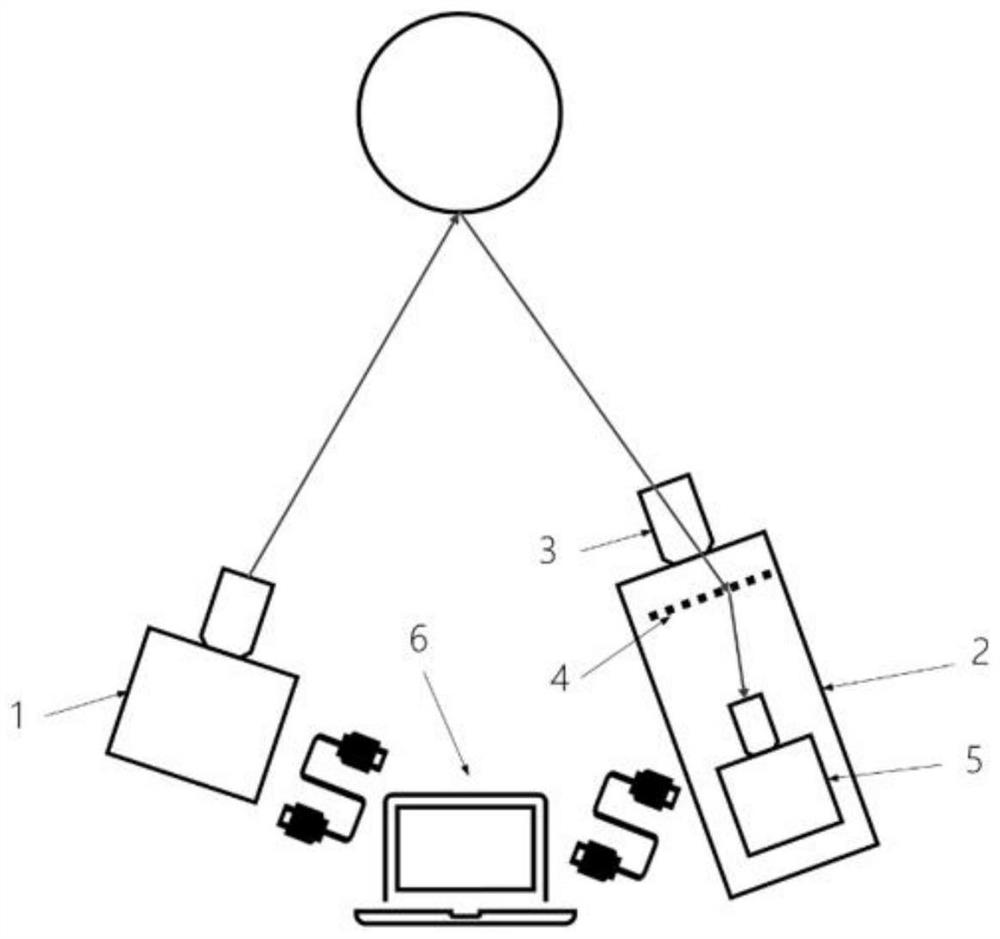
[0024] Such as figure 1 As shown, it is an adaptive projection moiré system for a continuous surface related to this embodiment, including: a projector 1 as a grid line projection system, a physical reference grating 4 arranged in a casing 2, a zoom lens 3, CCD camera 5 and the image processing control system 6 that is connected with projector 1 and CCD camera 5 respectively, wherein: image processing control system 6 outputs to projector 1 the raster line picture that needs projection and receives the picture that takes from CCD camera 5, Process and calculate the shape of the object by processing the moiré pictures captured by the camera.

[0025] In this embodiment, the zoom lens 3 adopts, but is not limited to, a zoom lens with a short focal length, which is used to receive the grating lines on the surface of the object and converge them on the reference grating. The zoom lens 3 is fixed on the housing 2 through a special bayonet.

[0026] The physical reference grating 4...


PUM


Abstract

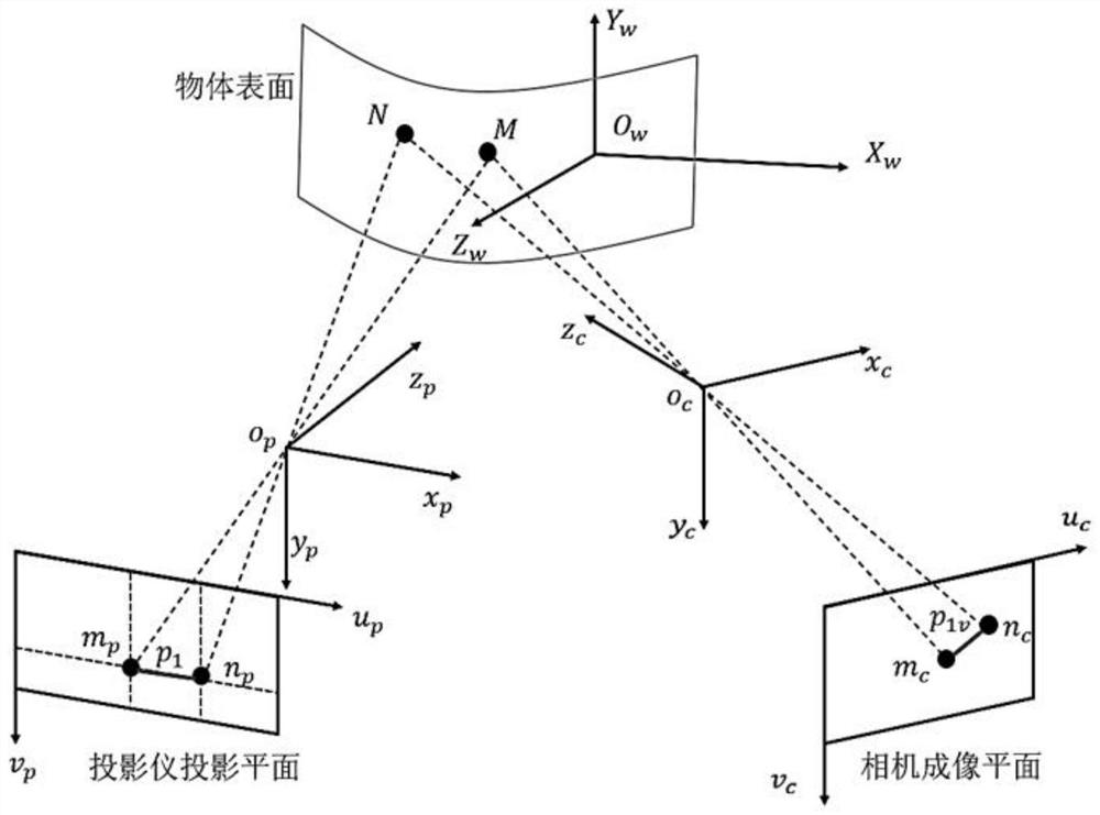
An adaptive projection moire method for a continuous surface comprises the following steps: measuring a three-dimensional initial shape of an object by using a projection moire technology through a calibrated real projector and a camera; constructing a virtual projection moire model according to the three-dimensional preliminary morphology and internal parameters and external parameters obtained through calibration, simulating a grid line pitch meeting a projection requirement in a virtual environment through an adaptive iterative algorithm based on preset ideal moire parameters, and generating a numerical grid line graph to be projected; and finally, projecting the numerical grid line graph to the surface of a measured object through a real projector, and collecting uniformly distributed moire images, thereby obtaining the accurate three-dimensional shape of the to-be-measured object. According to the invention, corresponding non-uniform projection grid lines and ideal uniformly-distributed adaptive moire patterns are generated for any measured object with a continuous surface, so that the measurement precision of the whole field is improved, and the measurement error distribution of the whole field is more uniform; te method is suitable for high-precision and high-resolution measurement of large-curvature objects, has no additional requirements on hardware, is low in energy consumption during working, and is suitable for field testing.

Description

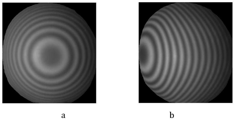
technical field [0001] The invention relates to a technology in the field of optical measurement, in particular to an adaptive projection moiré method for continuous surfaces. Background technique [0002] As a full-field optical measurement method, the projection moiré method forms a moiré grating with a lower density than the original projected grating, so it can amplify the phase change of the grating caused by surface deformation, thereby achieving a higher Phase resolution and measurement accuracy. However, the distribution of this moiré pattern is extremely uneven, and its non-sinusoidal phase error will be introduced in the area where the grid lines are dense, and the phase noise is relatively large in the area where the grid lines are sparse. The above two kinds of phase errors will make the measurement error in this area larger, so the measurement accuracy distribution of the whole field is uneven. Contents of the invention [0003] The present invention aims at...

Claims


Application Information

Patent Timeline
IPC IPC(8): G01B11/25G06T7/80G06T17/00
Inventor 孙晨蔡天宇陈巨兵马少鹏
Owner SHANGHAI JIAO TONG UNIV
Learn More