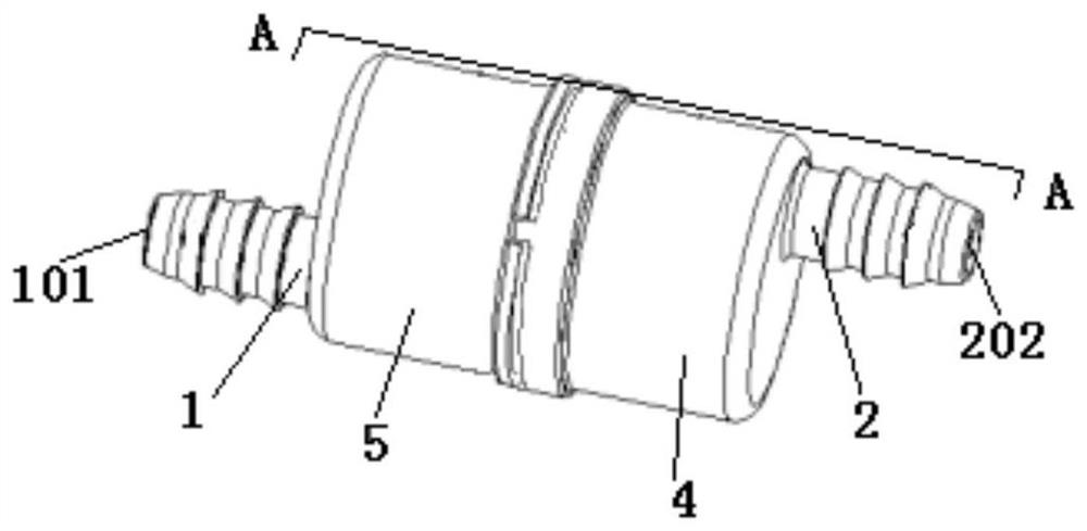
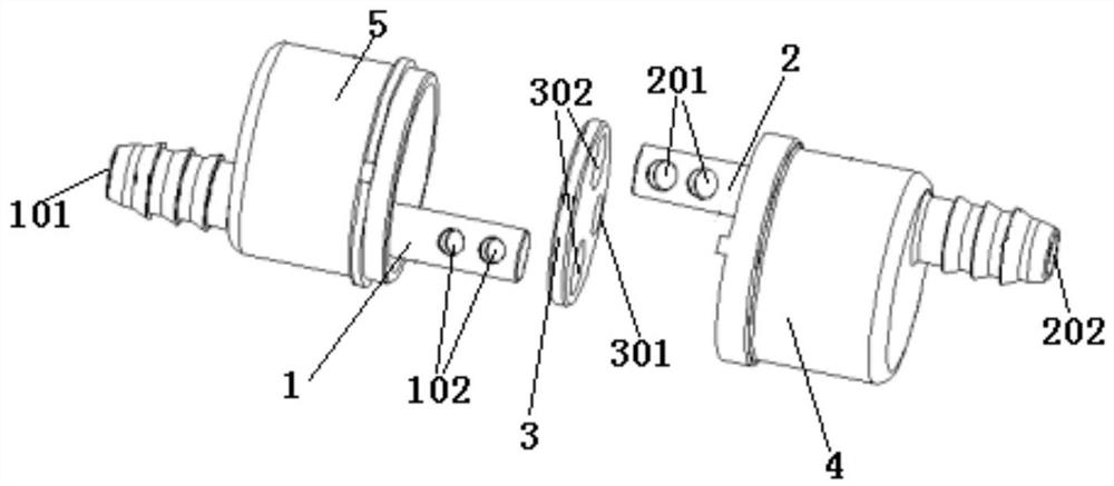
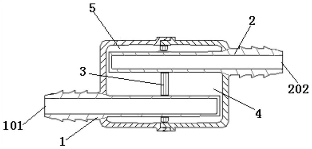
Noise reduction and vibration reduction device, brake vacuum pipeline and vehicle
A technology of vibration damping device and vacuum pipeline, which is applied in the direction of pipeline layout, etc., can solve the problems of large cross-sectional area of noise reduction and vibration damping cavity, affecting driving comfort, abnormal vibration and noise of one-way valve, etc., so as to avoid one-way valve. Abnormal noise, simple structure, and effective effect
- Summary
- Abstract
- Description
- Claims
- Application Information
AI Technical Summary
Problems solved by technology
Method used
Image

Examples
Embodiment Construction
[0040] Embodiments of the present invention will be described below with reference to the accompanying drawings and preferred embodiments, and those skilled in the art can easily understand other advantages and effects of the present invention from the content disclosed in this specification. The present invention can also be implemented or applied through other different specific implementation modes, and various modifications or changes can be made to the details in this specification based on different viewpoints and applications without departing from the spirit of the present invention. It should be understood that the preferred embodiments are only for illustrating the present invention, but not for limiting the protection scope of the present invention.
[0041] It should be noted that the diagrams provided in the following embodiments are only schematically illustrating the basic ideas of the present invention, and only the components related to the present invention ar...
PUM
 Abstract
Description
Claims
Application Information
 - R&D
- Intellectual Property
- Life Sciences
- Materials
- Tech Scout
- Unparalleled Data Quality
- Higher Quality Content
- 60% Fewer Hallucinations
Browse by: Latest US Patents, China's latest patents, Technical Efficacy Thesaurus, Application Domain, Technology Topic, Popular Technical Reports.
© 2025 PatSnap. All rights reserved.Legal|Privacy policy|Modern Slavery Act Transparency Statement|Sitemap|About US| Contact US: help@patsnap.com