


Quick Research
Generate reliable direction feasibility study reports for your R&D in just a few steps.

Technical Q&A
Discover and master advanced knowledge NOW. Basics, ideas, possibilities, all at once.

Find Solutions
As an expert in R&D theories, this can generate solutions to your technical problems instantly.

Evaluate Feasibility
Analyze your overall solution with one click, know your potential R&D risks in advance.

Monitor Landscape
Get weekly tech updates, stay abreast of the latest tech innovations and key insights.
Casting structure and method for diesel engine cylinder cover core assembly vertical casting process sand core combination
A technology of casting structure and cylinder head, applied in casting molding equipment, core, casting mold and other directions, can solve the problems of unfavorable castings, many casting defects, casting deformation, etc., to improve the degree of assembly automation, reduce sand casting defects , baking and impact reduction effects
- Summary
- Abstract
- Description
- Claims
- Application Information
AI Technical Summary
Problems solved by technology
Method used
Image

Examples
Embodiment 1
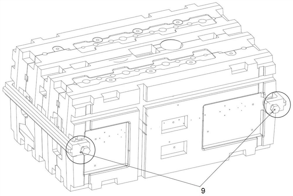
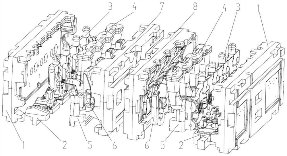
[0074] Such as figure 1 , 2 As shown, the casting structure of the diesel engine cylinder head group core vertical casting process sand core combination in this embodiment includes a tray core 1, an exhaust channel core seat 2, a water jacket core 3, an air intake channel core 4, and an exhaust channel core 5 , Upper water jacket core 6, left top cover core 7, right top cover core 8, clamping mechanism 9, a total of 12 sand cores and 1 set of clamping mechanism.
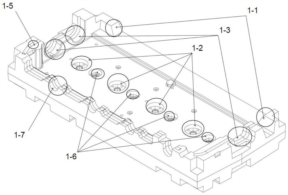
[0075] Such as image 3 As shown, the tray core 1 of this embodiment includes the exhaust side core seat 1-1 and the front and rear end core seats 1-3 of the lower water jacket, which are arranged on both sides of the bottom plate, and the air inlet round core seat 1-2 is arranged on the bottom plate. The front and rear end core seats 1-3 of the lower water jacket are also provided with a fire sealing ring 1-5, the air inlet round core seat 1-2 is provided with an exhaust duct round core seat 1-6, and one side of t...
Embodiment 2
[0115] The casting structure forming method of the present embodiment,
[0116] In this embodiment, the core-making process of the tray core 1, the left top cover core 7, the right top cover core 8 and the exhaust channel square core seat 2 is as follows:
[0117] Proportion: 10% of foundry silica sand with a particle size distribution of 50 / 100; reclaimed sand with a particle size distribution of 50 / 100: 90%; phenolic resin ratio (accounting for the total weight of the sand) 0.75%; ) 0.75%.
[0118] Phenolic resin and polyisocyanate temperature: 25°C. Sand mixing time: 60 seconds; the mixed sand should be used within 1 hour.
[0119] The core-making process of the inlet core 5 and the exhaust core 4 is as follows:
[0120] Proportion: 10% silica sand for foundry with particle size distribution 50 / 100; reclaimed sand with particle size distribution 50 / 100: 89.5%; anti-veining additive 0.75%; phenolic resin ratio (accounting for the total weight of sand) 1.05%; polyisocyanat...
Embodiment 3
[0128] In this embodiment, the core-making process of the tray core 1, the left top cover core 7, the right top cover core 8 and the exhaust channel square core seat 2 is as follows:
[0129] Proportion: 10% of foundry silica sand with a particle size distribution of 50 / 100; reclaimed sand with a particle size distribution of 50 / 100: 90%; phenolic resin ratio (accounting for the total weight of the sand) 0.8%; ) 0.8%.
[0130] Phenolic resin and polyisocyanate temperature: 35°C.
[0131] Sand mixing time: 65 seconds.
[0132] Requirements: The mixed sand should be used within 1 hour.
[0133] The core-making process of the inlet core 5 and the exhaust core 4 is as follows:
[0134] Proportion: 10% silica sand for foundry with a particle size distribution of 50 / 100; 89.5% reclaimed sand with a particle size distribution of 50 / 100; anti-veining additive 1%; phenolic resin ratio (accounting for the total weight of the sand) 1.1%; polyisocyanic acid Grease (accounting for the ...
PUM
 Abstract
Description
Claims
Application Information
 - R&D Engineer
- R&D Manager
- IP Professional
- Industry Leading Data Capabilities
- Powerful AI technology
- Patent DNA Extraction
Browse by: Latest US Patents, China's latest patents, Technical Efficacy Thesaurus, Application Domain, Technology Topic, Popular Technical Reports.
© 2024 PatSnap. All rights reserved.Legal|Privacy policy|Modern Slavery Act Transparency Statement|Sitemap|About US| Contact US: help@patsnap.com